In this part of the tutorial, create the flexible component that connects the base to the joystick handle.
Open the tutorial file (optional)
If you successfully completed part 2, you can proceed directly to the next step, Create the zigzag curve.
If you were not successful in part 2, open the file called joystick_Part2.wire, located in the wire folder of the CourseWare project. This file contains the completed model from part 2.
Create the zigzag curve
To create the profile for the sleeve, first create a simple curve across the gap between the handle and the base. Then, increase the number of CVs in the curve so a detailed zigzag shape can be created.
- Maximize the Left view. Choose Layouts > Left
 or F6.
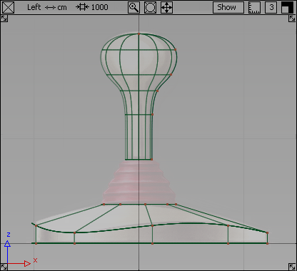
- Zoom in to the sleeve area.
Hold down the
 and
and  (Windows) or and
  (Mac) keys together and drag with the
  .
. 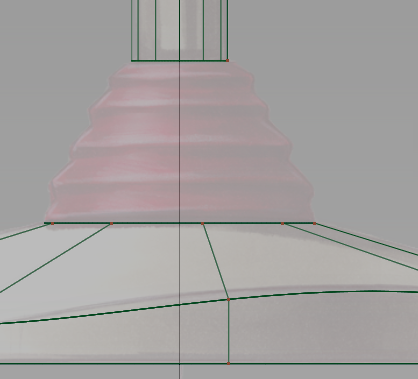
Start with a single span curve stretched across the gap between the bottom of the handle and the top of the base. Use curve snapping to place the sleeve curve accurately between the end of the handle and the base curves.
- Choose Curves > New Curves > New Edit Point Curve
 .
. - Place the first edit point.
Turn on edit point snapping by holding down the
 (Windows) or
  (Mac) and key. Click near the base of the handle. The edit point snaps to the corner.
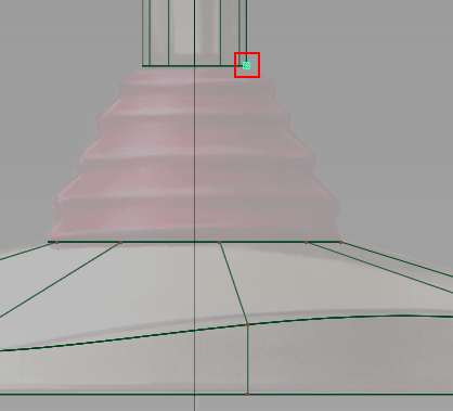
- Place the second edit point.
Keep the
(Windows) or (Mac) key held down and click near the top of the base. The edit point snaps to the corner. 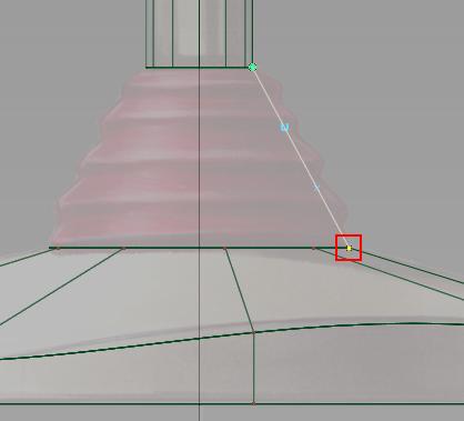
A single span curve is created that has two Edit Points (one at either end) and 4 CVs.
Note:The part of a curve between two edit points is called a span. A more complex curve with many edit points, has many spans, one between each pair of edit points. When a curve has more spans, it also has more CVs. These extra CVs can be used to create a more complex shape.
-
Now increase the number of CVs in this curve so you can create the zigzag profile of the sleeve.
In the Control Panel, the number of spans that make up the curve displays.

The curve currently has only one span.
In the Spans section of the control panel, type 8 and press
 (Windows) or
  (Mac).
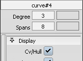
The curve is rebuilt with 8 spans, and now has 11 CVs. A preview of the rebuilt curve is shown in the view.
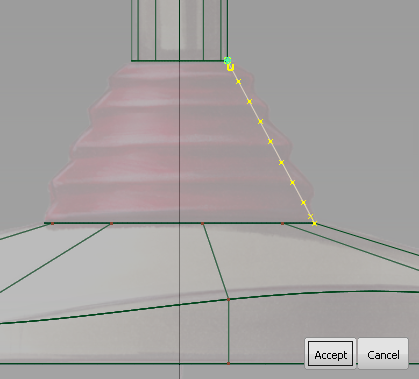
Click Accept to confirm the rebuild.
- Choose Pick > Nothing
 to deselect the curve.
 Next, select some of the CVs to move to shape the curve.
Looking at the top of the curve, the first CV is shown as a small square, and the second CV is shown as a U. Leave these two CVs unselected, so the sleeve profile stays connected to the handle, and the direction of the end tangent is not modified.
- Choose Pick > Point Types > CV
 .
. - Continue counting from the top and select the third, fifth, seventh, and ninth CVs.
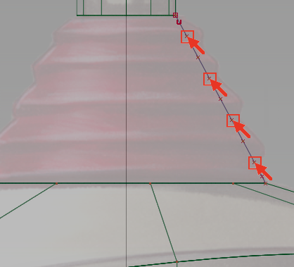
Leave the last two CVs unselected so the sleeve curve remains connected to the base profile, and the direction of the end tangent is not modified.
- Choose Transform > Move
 .
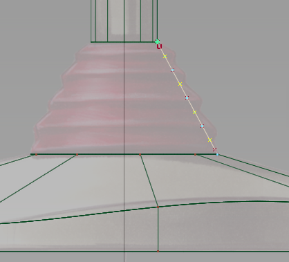
. - Drag with the
 to the right until a gentle zigzag shape is created, as shown.
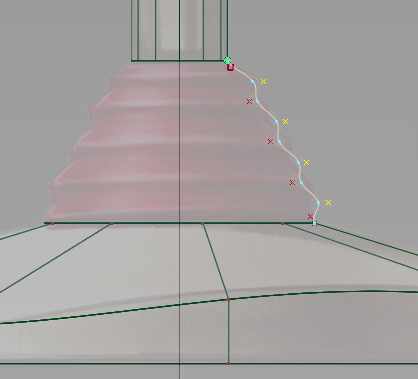
- With the CVs still selected, click the CV/Hull checkbox to turn off the CVs and hulls for the curve.
- Choose Pick > Nothing to deselect the CVs.
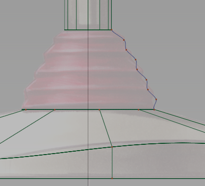
Next, create the sleeve surface.
- Choose Surfaces > Revolve
 .
. Double-click the Revolve icon. The Revolve control window opens.
Select Periodic and the default Degree value as 5 and the Spans value as 12.
Under Axis Options, select Global as the Axes and Z as the axis.
- Click the zigzag curve to revolve it around the Z axis.
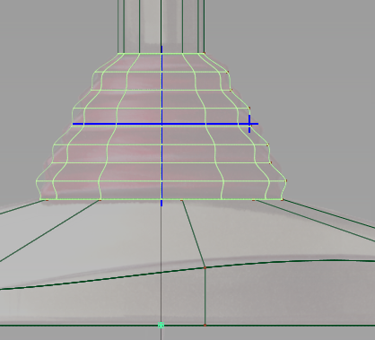
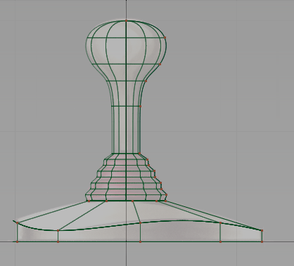
The surface is created. The blue manipulator that displays can be used to change the surface.
- Choose Pick > Nothing to deselect the surface.
The blue handles disappear.
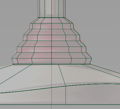
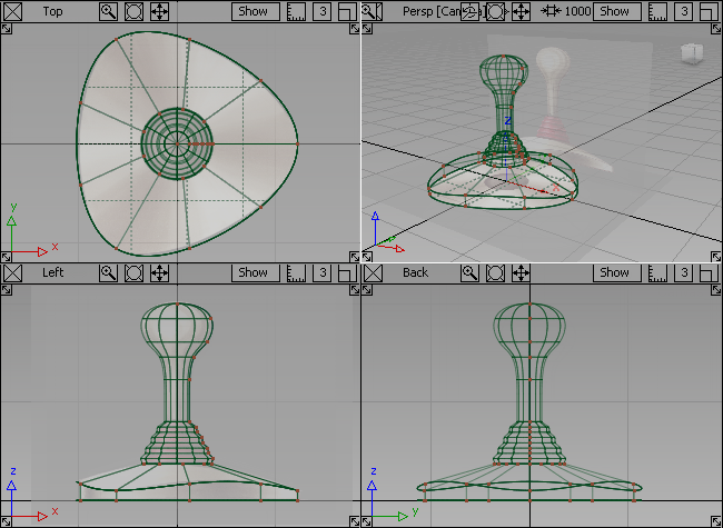
- Zoom out to view the whole joystick design.
- Press the F9 key to return to the four windows.
Save your work
- Choose File > Save As
 to save the current scene.
 - Save your work in the wire folder of the Lessons project.
- Name your file myjoystick3.wire.