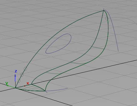
Now that you have intersected and trimmed the upper and lower surfaces, there is a sharp edge where the two surfaces meet.
To create a rounded transition between the two surfaces, create a fillet surface using the Surfaces > Surface Fillet![]() tool.
tool.
The surface fillet tool creates a rounded surface that blends smoothly between two surfaces, or two sets of surfaces. As well as creating the rounded surface, the Surface Fillet tool can also trim back the original surfaces to create a finished continuous form. This trimming is achieved using curves-on-surface, which the Surface Fillet tool creates automatically.
Open the tutorial file (optional)
If you successfully completed part 2, you can proceed directly to the next step, Create the body fillet.
If you were not successful in part 2, open the file called vacuum_Part2.wire, located in the wire folder of the CourseWare project. This file contains the completed model from part 2.
Create the body fillet
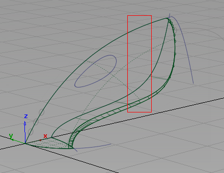
Next, create a fillet surface along the intersected edge of the vacuum cleaner body.
The Surface Fillet tool uses surface indicators to choose which side of a surface to create the fillet. These indicators are easier to see in a wireframe view. So first turn off the shaded view.
- Return to a wireframe view by clicking the wireframe icon in the Diagnostic Shade section of the Control Panel.
The upper surface only has lines showing on its edges.
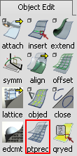
To improve the visualization of the surface, and to make it easier to select, increase the number of lines across the surface using the Patch Precision tool.
- Choose Pick > Object
 and select the upper surface. If the pick chooser appears, pick the rail surface, not the curve.
 - Choose Object Edit > Patch Precision
 .
. 
You are prompted to enter the number of curves per patch. Type 3 and press
 (Windows) or
  (Mac).
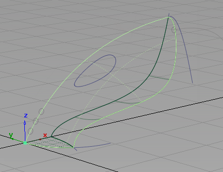
The surface now displays with some dotted lines across its interior. These dotted lines make the surface easier to visualize in wireframe, and can be used to select the surface.
Next, create the surface fillet along the trimmed edge where the two main surfaces meet.
- Choose Surfaces > Multi-Surface Fillet > Surface Fillet
 (if you are using Alias Design, Surfaces > Surface Fillet). Double-click the icon to open the option box.
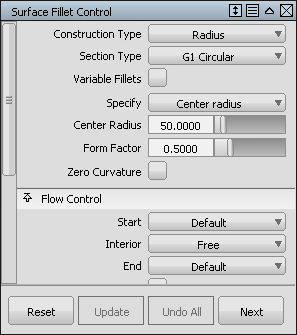
- In the Center Radius box, type a radius value of 37.5.
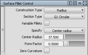
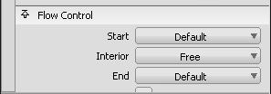
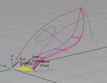
- In the Flow Control section, the Start and End options are set to Default.
For the Start and End, select Edge align.
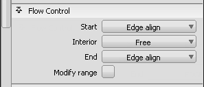
This choice ensures that the fillet surface is built to the full length of the edge, and the upper and lower surfaces are correctly trimmed.
- Close the Surface Fillet option box.
You are prompted to select the surfaces.
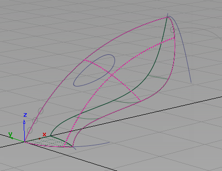
- Pick the upper surface.
If the pick chooser appears, select the rail surface.
The surface is selected and highlighted in pink.
- Click the lower surface to select it.
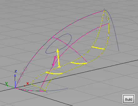
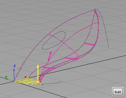
The surface is selected and highlighted in yellow, and a Build button appears in the bottom right corner of the view.
Arrows appear on both surfaces, indicating on which side of the surfaces the fillet will be built. If necessary, tumble the view to see which direction the arrows are pointing.
For the upper surface, the pink arrow should point inwards towards the inside of the vacuum cleaner body. If it is pointing out from the surface, then click it to reverse it.
The yellow arrow for the lower surface also should point inwards toward the inside of the vacuum cleaner body. If it is not, click it to reverse its direction.
- Click Build.
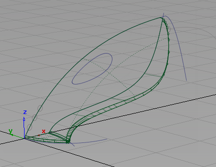
The fillet surface is created, and the upper and lower surfaces are trimmed.
- Choose Pick > Nothing
 to deselect all the surfaces.
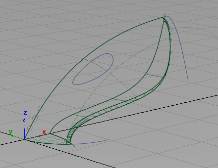
Create the nozzle fillet
The Surface Fillet tool can be used in different modes. The default mode, which you used for the body fillet, is to create a circular fillet. Circular fillet mode creates a constant radius surface along the length of the fillet surface.
For the nozzle, create a chordal fillet. A chordal fillet maintains a constant width of surface, instead of a constant radius. Chordal fillet mode produces a more regular surface when the angle between the two main surfaces varies along their edge.
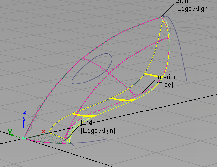
- Choose Surfaces > Multi-Surface Fillet > Surface Fillet (if you are using Alias Design, Surfaces > Surface Fillet). Double-click the icon to open the surface fillet option box. The flow control settings are currently set to Edge align for the start and end.
- Return the Flow Control settings to the default settings. On the drop-down menu for the Start and End settings, choose Default.
 Note:
Note:The ends of the fillet fall on the centerline of the vacuum design. As the edges of the main surfaces are already aligned to the centerline, the Surface fillet Edge Align adjustment is not required.
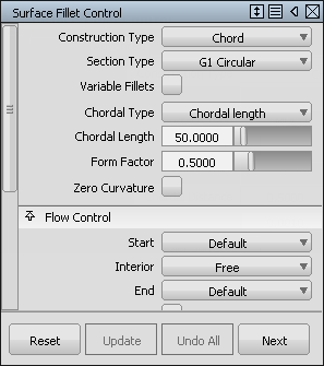
- For Construction Type, choose Chord from the drop-down menu to select a constant width fillet.
- For Chordal Type, choose Chordal length.
- Only a small fillet is required around the nozzle, so set Chordal Length to 50.
Close the Surface Fillet option box.
You are prompted to select the input surfaces.
- Drag a pick box around the upper, lower, and fillet surfaces, avoiding the planar surface.
All three surfaces are selected and highlighted in pink.

- Click the planar surface to select it.
If the pick chooser appears, pick the trim_surface.
The surface is selected and highlighted in yellow.
Arrows appear on both sets of surfaces, indicating on which side of the surfaces the fillet will be built. The arrows should point in towards the inside of the vacuum body. If an arrow is pointing out of the surface, click the arrow to reverse it.
- Click Build.
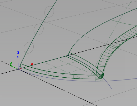
The chordal fillet surface is created, and the surfaces trimmed to create a smooth, continuous exterior.
- Choose Pick > Nothing to deselect all the surfaces.
Save your work
- Choose File > Save As
 to save the current scene.
 - Save your work in the wire folder of the Lessons project.
- Name your file myvacuum3.wire.