Creates one or more ruled surfaces by pulling a group of surface curves at an angle to the normal of the original surface(s), or by pulling any number of curves at an angle to a pull vector. The curves can be continuous or disjoint.
The Multi-Surface Draft tool uses surface edges, curves on surface, isoparametric curves, and in Draft mode, even free curves, to create a ruled surface (or group of surfaces) that extends away at an angle to the original surface (or curve).
You can build a single surface across all of the input curves, provided that they are tangent continuous.
Procedures
Multi-Surface Draft Control options
- Type
-
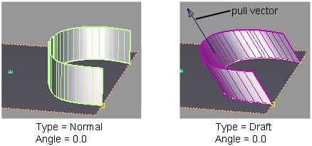
Normal – Creates a surface that extends away at a given angle from the normal of the underlying surface(s). By default, the new surface is normal to the underlying surface(s).
Draft – Creates a surface that extends away at a given angle from a specified pull direction vector. By default, the surface is parallel to the pull vector.
In this mode, you can individually select, or box-select, any combination of curves (even free curves), whether they are disjoint (non-touching), G0 (position continuous) or G1 (tangent continuous).
- Angle/Draft Angle
-
The initial angle between the new surface and the normal of the original surface (Normal type), or pull vector (Draft type). The default is 0.0. You can also change this value using the angle/length manipulator when you use the tool. (See Variable option below).
- Length
-
The initial length of the surface from the original curves. You can also change this value using the angle/length manipulator when you use the tool. (See Variable option below).
- Double Sided
-
Turn this option on to build draft surfaces on both sides of a curve simultaneously.
- Single Surface
-
This option only appears if Double Sided is on. Turn it on to build only one surface, extending on both sides of the curve.
- Intersect Flanges
-
Turn on this option to handle corner conditions when two flange or draft surfaces meet. The surfaces will be trimmed or extended so that they join properly at corners.
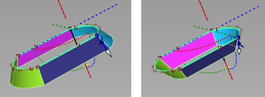
Left: draft angle = 35; surfaces are extended, intersected and trimmed. Right: draft angle = -35; surfaces are intersected then trimmed.
- Flip
-
Reverses the direction of the new surface(s).
- Explicit Control
-
Turn on this option if you want to specify the exact degree and maximum number of spans in the new surface(s).
Explicit Control Options
- U Degree
-
Degree of the new surface(s) in the U direction. Enter a whole number from 2 to 9. This option only appears if Explicit Control is checked.
- V Degree
-
Degree of the new surface(s) in the V direction. (The surfaces are always of degree 1 in the V direction.)This option only appears if Explicit Control is checked.
- Max. Spans
-
If Surface Type is set to Multiple surfaces, this value specifies the maximum number of spans for each draft surface. If Surface Type is set to Single surface, it specifies the maximum number of spans for each piece of the original surfaces.
This option only appears if Explicit Control is checked, and Bézier Surfaces is not checked.
Draft Vector Options
These options only apply when Type is set to Draft.
- X,Y, Z
-
Select one of these to specify a pull direction along that axis.
- View
-
Select this option to specify a pull direction normal to the current view. The vector is not drawn in the view windows.
If the current view is changed, click Refresh View Vector to update the vector.
- Picked
-
Selecting this option lets you specify the name of an existing vector in the Picked Vector field, or pick the vector in the view. This vector defines the pull direction.
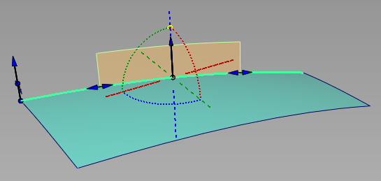
- Manip
- This option is selected automatically when you update the pull direction by manually modifying the manipulator in the view.
- Refresh Vector
-
This button only appears if View is selected. Click it to update the vector if the view has been modified.
- Retain Vector
-
Click this button to create a vector construction object in the view windows. Unless you do this, the vector direction you specified is used by the tool, but you will not see and be able to re-use the vector.
Note
When Type is set to Draft in the control window, and Draft Vector Options is set to X, Y, or Z, the tool uses the X, Y, and Z axes from the construction plane, if one is set.
The following rules apply:
- Draft surface direction always respects the current coordinate system.
- If a draft surface was created in one set of coordinates (construction plane), and is later query-edited in a different one, the Refresh Vector button can be clicked to update the draft direction.
Modify Range
- Modify Range
-
When this option is checked on, Start and End sliders appear in the control window, and arrow manipulators appear on the draft surfaces. Drag these arrows to modify the extent of the draft surfaces across the input curves.
When this option is checked off, the draft surfaces extend to the ends of the input curves.
- Start/End
- Use these sliders to modify the extent of the draft surfaces. Start and End values of 0.0 and 1.0 respectively, define the original extent.
Range of draft surface (in orange) extends from 0.25 (Start) to 0.75 (End).
Surface Structure
- Surface Type
-
If you choose Single surface, a single surface is built. If you choose Multiple surfaces, a separate surface is created for each of the input curves you selected, and the surfaces are grouped.
Note:Creating a single surface might add additional spans.
- Bézier Surfaces
-
This option only appears if Surface Type is set to Multiple surfaces. If it is checked on, each surface will be a Bézier patch.
Bézier patches have a single span, and their maximum degree in the U direction is set through the Explicit Control section. The default is the degree of the input curve.
Pick Mask
These options let you choose what types of curves are selectable as input. This is especially useful when using box selection.
- Surface Isoparm
- Check this option to make surface isoparms selectable as input.
- Surface Trim Edge
- Check this option to make surface trim edges selectable as input.
- Curve
-
Check this option to make free curves selectable as input.
This option only appears when Type is set to Draft.
- Curve-on-surface
- Check this option to make curves-on-surface selectable as input.
Control Options
- Auto Update
-
Turn on this option to have the new surface automatically re-calculated and displayed as you modify the option values or make adjustments to the manipulators.
If it is off, you must click the Update button in the lower right corner of the window to update the surface(s).
Tip:If Auto Update is turned off, you can also use the spacebar to click the Update button.
- Inter Surface Continuity
-
Checking on this option displays continuity locators between the output surfaces, indicating whether or not they are tangent continuous. Green T locators indicate that the surfaces are tangent continuous while red/yellow T locators indicate they are not.
The Continuity Angle fromPreferences > Construction Options is used when testing for tangent continuity, and a shared boundary is only checked if it doesn't present any gap larger than the Topology Distance tolerance (also found in Construction Options).
Only natural (non-trimmed) edges are checked.
- Tangent Angle Maximum
- This option is only available when Inter Surface Continuity is checked on. It is used to exclude "corners" from the check. If, at any check point along a shared boundary, the angle between surface normals is larger than this value, then tangent continuity is not reported along that boundary. The default is set to 30.0 degrees.
- Continuity Check
-
Turn on this option to check for positional continuity between the newly created surface(s) and the original surface(s). A green P means positional continuity exists.
- Chain Select
-
If this box is checked, selecting a surface curve also selects all other surface curves that are tangent continuous with it.