Lists the sheet metal rules in the active document or global style library (depending on the filter setting of Local or All Styles). Specifies selections and values associated with: Sheet, Bend, and Corner options for sheet metal features.
Access
Click
Manage tab
 Styles and Standards panel
 Styles Editor
![]()
In the browser pane, click Sheet Metal Rule, and then click the sheet metal rule name to display the selections and values on each Sheet, Bend, and Corner tab in the right portion of the dialog box.
![]() Click the expand/collapse “+” to the left of the Sheet Metal Rule entry in the left-hand portion of the Style and Standard Editor dialog box to display the list of existing rules. Select an existing sheet metal rule to display its option settings.
Click the expand/collapse “+” to the left of the Sheet Metal Rule entry in the left-hand portion of the Style and Standard Editor dialog box to display the list of existing rules. Select an existing sheet metal rule to display its option settings.
Back - return to the previously edited style. You are prompted to save the previous edits.
New - create new styles. Select the Add to Standard check box to add to the available styles list in the active standard style.
Save - save changes to an existing style in the current document.
Reset - return style values to the saved values.
Location Filter - show Local Styles or All Styles (from the library) in the browser.
Sheet Tab
Sheet
Material - listing of available materials. If the Style and Standard Editor filter is set to ‘local styles’ - only material styles present in the local document will be visible. If the Style and Standard Editor filter is set to ‘All Styles’ - the material list control will show all available materials, without any restrictions on whether a material is a plausible sheet metal material or not (i.e. glass).
![]() Edit Material - Provides access to the Style and Standard Editor and allows the material to be edited.
Edit Material - Provides access to the Style and Standard Editor and allows the material to be edited.
Thickness - Field allows entry of a material thickness (as a numeric value or evaluated expression).
Unfolding Rule - select from a list of unfold rules defined including linear KFactor rules or bend tables.
![]() Edit Unfold Rule - Provides access to the Style and Standard Editor and allows the unfold rule to be edited.
Edit Unfold Rule - Provides access to the Style and Standard Editor and allows the unfold rule to be edited.
Miter/Rip/Seam Gap - Field allows the entry of a value or parameter to specify the default gap size.
Flat Pattern Bend Angle
Two optional selections which determine how angles are to be measured:
- Report Bending Angle (A) - Measures angles as indicated by the blue dimension arrow in the illustration labeled “A”.
- Report Open Angle (B) - Measures angles as indicated by the red dimension arrow in the illustration labeled “B”.

Flat Pattern Punch Representation
Four options that determine how Sheet Metal Punch iFeatures are displayed when the folded model is displayed as a flat pattern.
![]() Formed Punch Feature Select this option to display Sheet Metal Punch iFeatures as fully three-dimensional features in the flat pattern.
Formed Punch Feature Select this option to display Sheet Metal Punch iFeatures as fully three-dimensional features in the flat pattern.

![]() 2D Sketch Representation -Select this option to display Sheet Metal Punch iFeatures using a previously defined 2D sketch of the feature when the model is displayed as a flat pattern.
2D Sketch Representation -Select this option to display Sheet Metal Punch iFeatures using a previously defined 2D sketch of the feature when the model is displayed as a flat pattern.

![]() 2D Sketch Rep and Center Mark Select this option to display Sheet Metal Punch iFeatures using a previously defined 2D sketch with center mark when the model is displayed as a flat pattern.
2D Sketch Rep and Center Mark Select this option to display Sheet Metal Punch iFeatures using a previously defined 2D sketch with center mark when the model is displayed as a flat pattern.

![]() Center Mark Only Select this option to display Sheet Metal Punch iFeatures using only the sketch center mark when the model is displayed as a flat pattern.
Center Mark Only Select this option to display Sheet Metal Punch iFeatures using only the sketch center mark when the model is displayed as a flat pattern.

Bend Tab
Relief Shape
Use this option to define the Default relief shape that is created for all features which create a bend.
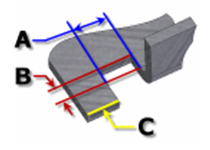
![]() Straight A bend relief shape defined by square corners. It is common in manual shop situations and often produced by a saw kerf. In the following illustration, A indicates the bend relief width, B indicates the bend relief depth beyond the deformation zone, and C represents the size of the material remnant left following the creation of the bend with relief. Each of these parameters define the bend relief defaults.
Straight A bend relief shape defined by square corners. It is common in manual shop situations and often produced by a saw kerf. In the following illustration, A indicates the bend relief width, B indicates the bend relief depth beyond the deformation zone, and C represents the size of the material remnant left following the creation of the bend with relief. Each of these parameters define the bend relief defaults.
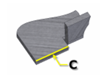
![]() Tear An acceptable bend relief resulting from material failure. It is common when tight bends are required and with certain materials. In the following illustration, C represents the size of the material remnant left following the creation of the bend with relief. This parameter defines this value.
Tear An acceptable bend relief resulting from material failure. It is common when tight bends are required and with certain materials. In the following illustration, C represents the size of the material remnant left following the creation of the bend with relief. This parameter defines this value.
![]() Round A bend relief shape defined by a cut ending with a semicircle. It is often produced using laser cutting technology. In the following illustration, A indicates the bend relief width (diameter), B indicates the bend relief depth beyond the deformation zone to the tangent point of the diameter, and C represents the size of the material remnant left following the creation of the bend with relief. Each of these parameters define the bend relief defaults.
Round A bend relief shape defined by a cut ending with a semicircle. It is often produced using laser cutting technology. In the following illustration, A indicates the bend relief width (diameter), B indicates the bend relief depth beyond the deformation zone to the tangent point of the diameter, and C represents the size of the material remnant left following the creation of the bend with relief. Each of these parameters define the bend relief defaults.
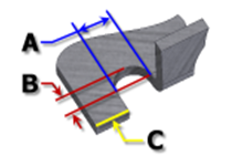
Relief Width Value that defines the width of the bend relief as the named model parameter: BendReliefWidth and is identified as A in the dialog box illustration.
Relief Depth Value that defines the depth of the bend relief as the named model parameter: BendReliefDepth and is identified as B in the dialog box illustration.
Minimum Remnant Value field that defines an acceptable size for the minimum stock allowed to remain along side of a bend relief cut (any remainder smaller is eliminated from the model). Stored as the named model parameter: MinimumRemnant.
Bend Radius Value that defines the radius of bend features as the named model parameter: BendRadius
Bend Transition
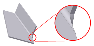
Use the Bend Transition option to define one of five geometry conditions that is shown in the flat pattern of the bend. The folded model either shows the transition type of None (for all transition types except Trim) or the type Trim if that is the selected type.
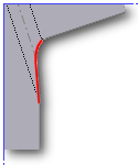
![]() None - Depending on the geometry, results in a spline between the edges of the 2 faces meeting at the selected bend. In the following illustration, the portion of the flat pattern showing this transition type is illustrated for the folded model shown previously.
None - Depending on the geometry, results in a spline between the edges of the 2 faces meeting at the selected bend. In the following illustration, the portion of the flat pattern showing this transition type is illustrated for the folded model shown previously.
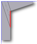
![]() Intersection - Results in a straight line from the edge of the bend zone that intersects the edge of the bent feature. In the following illustration, the portion of the flat pattern showing this transition type is illustrated for the folded model shown previously.
Intersection - Results in a straight line from the edge of the bend zone that intersects the edge of the bent feature. In the following illustration, the portion of the flat pattern showing this transition type is illustrated for the folded model shown previously.
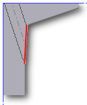
![]() Straight Line - Results in a straight line from 1 edge of the bend zone to the other. In the following illustration, the portion of the flat pattern showing this transition type is illustrated for the folded model shown previously.
Straight Line - Results in a straight line from 1 edge of the bend zone to the other. In the following illustration, the portion of the flat pattern showing this transition type is illustrated for the folded model shown previously.
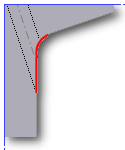
![]() Arc - Requires entry of an arc radius value and results in an arc of that size tangent to the edge of the bent feature and what would be a straight transition. In the following illustration, the portion of the flat pattern showing this transition type is illustrated for the folded model shown previously.
Arc - Requires entry of an arc radius value and results in an arc of that size tangent to the edge of the bent feature and what would be a straight transition. In the following illustration, the portion of the flat pattern showing this transition type is illustrated for the folded model shown previously.
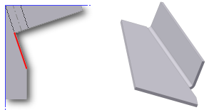
![]() Trim to Bend - This type of transition is displayed in the folded model and results in a cut to the bend zone perpendicular to the bent feature. In the following illustration (left), the portion of the flat pattern showing this transition type is illustrated for the folded model shown on the right.
Trim to Bend - This type of transition is displayed in the folded model and results in a cut to the bend zone perpendicular to the bent feature. In the following illustration (left), the portion of the flat pattern showing this transition type is illustrated for the folded model shown on the right.
Corner Tab
2-bend Intersection
Use this option to define the Default corner relief when two bends intersect.
Round A corner relief shape defined in the flat by a circular cut out centered on the intersection of the bend lines.
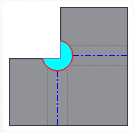
Square A corner relief shape defined in the flat by a square cut out centered on the intersection of the bend lines.
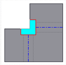
Tear A corner relief shape defined in the flat by extending the flange edges to their intersection. Characterized by no relief which allows material failure (tearing) across the bend zone in the folded model.
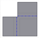
Trim to Bend A corner relief shape defined in the flat by a polygonal cut out bounded by the bending zone lines.
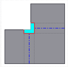
Linear Weld A corner relief shape defined in the flat by a V-shaped cut out defined from the intersection of the inner bend zone lines to the outer bend zone intersection of the line with the flange edges. Characterized by minimum relief allowing a subsequent weld operation to close the corner.
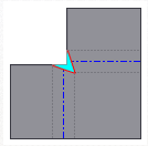
Arc Weld A corner relief shape defined in the flat by spline curves from the outside edge of the bend zone which converge to a flat gap equal to the Miter Gap value. Characterized in the folded model by a gap between the flanges that is equidistant along the length of the relief suitable for subsequent arc welding.
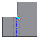
Relief Size Parameter field to define the size of the Corner Relief system parameter: CornerReliefSize. This parameter is used by default for all 2-bend corners.
3-bend Intersection
Use this option to define the Default corner relief to display in the flat pattern when 3 bends intersect.
No Replacement As indicated, no replacement of the "as modeled" geometry is made in the flat pattern.
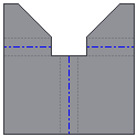
Intersection A corner relief shape defined in the flat by extending and intersecting the flange edges.
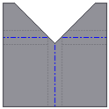
Full Round A corner relief shape defined in the flat by extending the flange edges to their intersection and then placing a fillet tangent to the bend zone tangency lines. Radius is likely larger than what is produced using the Round with Radius option.
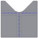
Round with Radius A corner relief shape defined in the flat by extending the flange edges to their intersection, and then placing a tangent fillet of the size specified. Radius is likely smaller than what is produced by the Full Round option.
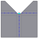
Radius Size Parameter field to define the default size of the Corner Relief radius. Available for equations using the named parameter: JacobiRadiusSize.
Import - use to import a style exported from another document.
Done - after saving changes, click to dismiss the Styles and Standard Editor dialog box.