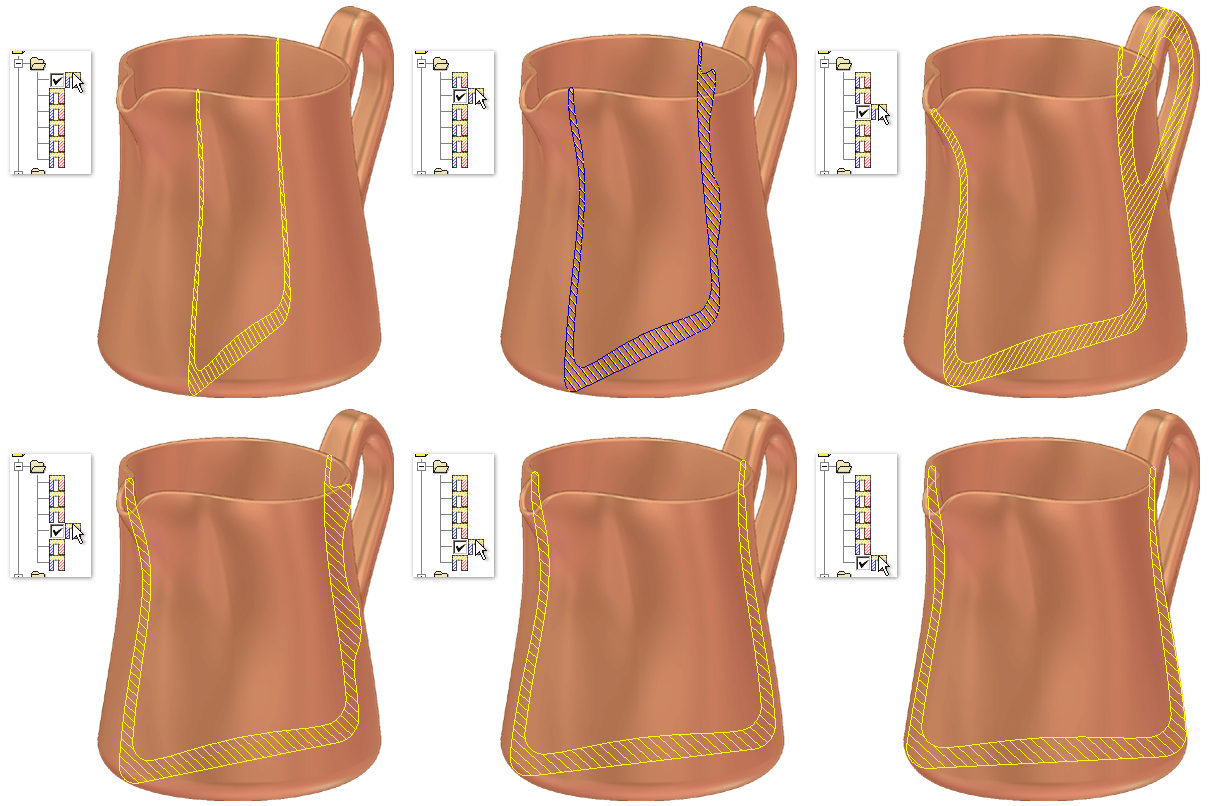
The following animation shows how you can select saved cross sections in the browser. Press F5 to replay the animation.

Create simple cross section analysis
- Open a part file or double-click a part in an assembly to edit the part in-place.
- On the ribbon, click
Inspect tab
 Analysis panel
 Section
. Tip: After the initial analysis is saved, you can right-click the Analysis folder in the Model browser, and then select New Cross Section Analysis from the context menu.
 - If appropriate, enter a custom name. Tip: After the initial analysis is saved, you can slow double-click the analysis in the Model browser to change the name.
- Click Simple to indicate the type of cross section analysis.
- Select a planar face or work plane to start the plane definition.
- Optionally, click the direction arrow or drag the plane in the other direction to change the direction from the default.
- In the graphics window, click and drag the plane, or enter a value for the Section Offset.
- Click OK to analyze. If you prefer, click Apply to analyze and keep the dialog box open, and then continue to change settings and analyze as needed.
Create advanced cross section analysis
- Open a part file or double-click a part in an assembly to edit the part in-place.
- On the ribbon, click
Inspect tab
 Analysis panel
 Section
. Tip: After the initial analysis is saved, you can right-click the Analysis folder in the Model browser, and then select New Cross Section Analysis from the context menu.
 - If appropriate, enter a custom name.
- Click Advanced to indicate the type of cross section analysis.
- Section plane options:
- Use Create to select one planar face or work plane which is offset at a specified count and spacing to define the orientation of parallel analysis cross sections. Proceed to next step.
- Use Select to select multiple workplanes and planar faces. Using the Select method omits the need to specify an offset values. Proceed to Step 10.
- Set the number of sections to analyze.
- Optionally, click Flip to reverse the direction of the sections.
- Optionally, click the mid plane check box to distribute the section planes on both sides of the original plane. Note: When the number of sections is even, use Flip to determine which side gets the extra section.
- Select the section spacing method and the section spacing:
- Select Distance to specify the total distance to be covered by the sections.
- Select Spacing to specify the spacing between sections.
- Set the minimum and maximum wall thickness for the analysis. The thickness values are a linear distance that represents the minimum and maximum wall thickness for the part.
- Click Calculate to analyze and keep the dialog box open.
- Use the filter check boxes to control the information that is displayed in the Results tab and the graphics window. You can:
- Display all sections.
- Hide all sections.
- Display violating sections only.
- Double-click the visibility column for that section to change visibility of one or more sections. Use the Next Section arrows to move the row selection up or down.
- Click OK to close the dialog box.
Interpret results
Use the filters to control the information that is displayed in the results tab and the graphics window. You can display all sections, hide all sections or display violating sections only. Use the Next Section arrows to change the row selection up or down.
Customize display of results table- Click Column Chooser.
- Drag the fields from the Customization dialog box into the Results table to add additional fields to the table.
- Drag a field from the table into the Customization dialog box to remove fields.
Cross section graphics
Each section marked as visible in the results table is a crosshatched section in the cross section of the part.
- Sections that violate the minimum or maximum thickness are displayed in the corresponding row color.
- Adding any of the physical properties columns using the Column Chooser enables the visibility of the centroid glyph for each section
Pause the cursor over the sections in the graphics window to view a tooltip that includes the section number, area, and whether it is greater than or less than the minimum or maximum thickness.