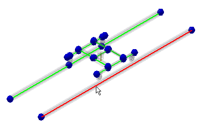
We also insert custom nodes to the rails under the cart wheels. Later, we use all these nodes to create rigid links.
- In the Connections panel, click Custom Node
 .
. - Select the beam as shown on the image.

- Enter 6080 mm to the Offset edit field and click Done
 . Insert a second custom node to the same beam. Right-click and select Repeat Custom Node. Select the same beam, enter 3920 mm and click Done
  .
. - Now, we insert custom nodes to the parallel beam. In the Connections panel, click Custom Node
 .
. - Select the beam as shown on the image.

- Enter 6080 mm to the Offset edit field and click Done
 . Insert a second custom node to the same beam. Right-click, and select Repeat Custom Node. Select the same beam, enter 3920 mm and click Done
  .
.
We inserted all custom nodes that we need for our analysis. Custom Nodes are listed in the Nodes folder in the browser. Their numbers were assigned in the order we defined them, starting from the first available node number.
Note: You can also display the node numbers in the graphics window. In the Display panel, click Node Labels .
.