Next, we add nodes to the selected beams of the frame structure. Custom nodes are used for defining the loads, constraints, releases, and rigid links.
- In the Connections panel, click Custom Node
 . A Heads Up Display (HUD) is used as the default edit method. It prompts you to select a beam where we place the custom nodes.
 - Select the beam as shown in the following image.
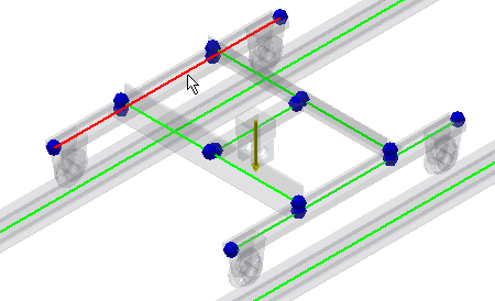
- Enter 170 mm to the Offset edit field and click Done
 . Repeat the same steps to insert a second custom node to the same beam. Click the Custom Node command, select the beam, enter 2330 mm and click Done .
 - Now, we insert custom nodes to the parallel beam. In the Connections panel, click Custom Node.
- Select the beam as shown on the image.
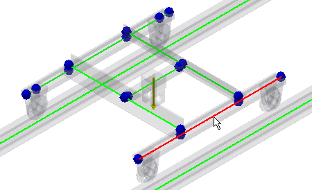
- Enter 170 mm to the Offset edit field and click Done . Repeat the same steps to insert a second custom node to the same beam. Click the Custom Node command, select the beam, enter 2330 mm and click Done .