-
 On the ribbon, click
Pipe Run tab
 Route panel
 New Route
.
 - On the Create New Route dialog box, accept the default route file name and location, and click OK.
A pipe route is added to the active run and activated. The Route tab displays on the ribbon.
-
 On the ribbon, click
Route tab
 Create panel
 Route
.
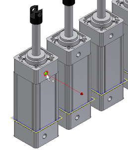
 - In the graphics window, zoom in the model. Then pause the cursor over the circular geometry of the first Air Cylinder as shown in the following image. If appropriate right-click and click Select Other Direction.

- Click the circular geometry to select it as the start point.
This point is associated with the component that contains the selected circular edge. A work point is added to the piping route.
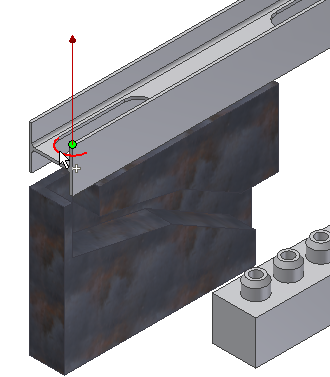
- For the second route point, select a point on the line extender or existing geometry. To route through the IBeam, pause the cursor over the left arc of the IBeam opening.

Rotate and zoom in to view the arc. Make sure that the line is pointing to the approach direction of the route.
Note: To flip the direction of a displayed axis, press the spacebar or use the Select Other tool. - Click the geometry to select it as the second point.
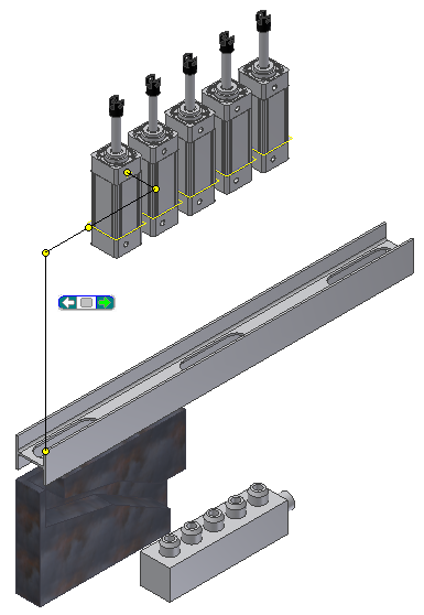
As soon as you make your selection, the route generates to that point and the Select Other tool appears indicating that multiple solutions exist. Click the arrows to cycle through the solutions.

- Click the green area in the Select Other tool to select the solution from the previous image.

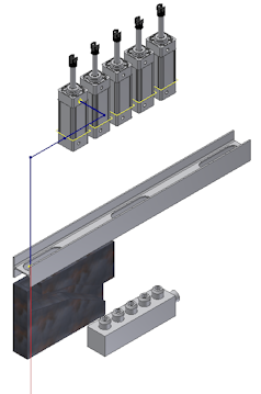
- In the Model browser, verify that the Autoroute browser node is added and contains five route points.
