 |
|
When you add hole notes to a drawing view, the diameter, depth, thread dimensions, and other data from the model are used in the note. If hole features are changed in the model, the hole notes update when the drawing is updated.
If a view update removes a circular edge that the note is attached to, it reattaches to the outermost circular edge of the hole feature. In a side view, the note reattaches to the nearest edge to the original attachment point.
In addition to individual holes, a hole note can be added to extruded cuts (except midplane extrusions), and holes in iFeatures, patterns, and sheet metal flat patterns.
Notes:
- Note leader lines snap in 15-degree steps. Hold the CTRL key on your keyboard to disable leader line snapping. Then place or move the leader line to the desired position.
- In side views, you can select linear edges to position a hole or thread note.
- If you place threads on an extruded cut hole, your selection of the thread or hole edge determines if a thread or hole note is created.
- You cannot create hole and thread notes in slice section views.
- Thread features are not displayed in raster drawing views. New or existing thread notes are attached to thread features after views turn precise.
Linear dimension thread notes in side views
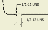 |
You must select a valid pair of thread edges to define a linear dimension thread note. The appearance of linear dimension thread notes is determined by default style for linear dimensions. |
Setting the format for hole notes
The default format and content of hole notes is controlled by the hole note's associated dimension style. On the Notes and Leaders tab of the dimension style, define hole note formats for each hole and thread type before you start working on a drawing.
Overriding the format for a hole note
You can control format, content, and other attributes of an individual hole note one of these ways:
- Apply a different dimension style to change the formatting and content. The hole note updates to the format for the new dimension style.
- Edit the hole note to change the formatting and content. You select a hole note in a drawing view, right-click, and then select Edit Hole Note. The settings are the same as the settings specified in the style, but you can change the values for the current hole only. Changes are not reflected in the dimension style.
- Edit the hole note dimension style. Any change in formatting applies to all hole notes associated to the dimension style.
Replacing a hole note with text
You can hide the contents of an individual hole note and replace it with text that is associated to the drawing view.
Dual dimension units in hole notes
Hole notes can display dimension values in alternate units. The dual units display is set on the Alternate Units tab of the dimension style. You select a stacked or linear display format for dual unit dimensions.