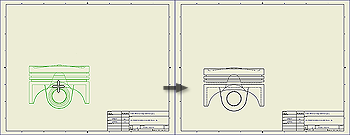
The first view in a new drawing is a base view. On the ribbon, click
Place Views tab
 Create panel
 Base
to add additional base views to a drawing.
A base view is the source for subsequent views. A base view:
- Sets the defaults for child views.
- Can be used to create a projected view, an auxiliary view, a section view, and a detail view.
|
|
- On the ribbon, click
Place Views tab
 Create panel
 Base
.
- On the Component tab, set up the view:
- Specify the model or presentation file.
Note: The Base View command by default selects the last active model document as the source for the placed view. If the last active model document is closed, no model is automatically selected.
- To specify the model file, click the drop-down arrow next to File. Select Open an existing file to browse for a non-vaulted file. Select Open from Vault to browse for a file in the vault.
Note: You can create a view of a part that contains only sketches. 2D sketches must be parallel to the view.
- Depending on the file type, you can also select the
design view representation
, iAssembly member, positional representation, level of detail representation, sheet metal view,
weldment group
, or
presentation view
.
- Select the view orientation from the list, or click Custom View to set up a nonstandard view.
- On the Model State tab, set the weldment state or iAssembly or iPart member to use in a drawing view. Available options depend on the type of file used to create the view.
- On the Display Options tab, set reference and display options for the view. Available options depend on the type of file used to create the view.
- Set the additional options:
- Specify the view scale, and switch the visibility of the view label in the drawing on or off. If needed, click Edit View Label to edit the view label in the Format Text dialog box.
- Make sure the Create projected views immediately after base view creation box is checked if you want to create a base view and projected views at the same time.
- In the graphics window, move the preview to the appropriate location, and then click to place the view.
|
|
|
Note: Parts with the BOM Structure set as Reference are not included in the formula for creating the default size of the view bounding box. As a result, the Reference parts can be clipped in drawing views. To extend the size of the view bounding box, increase the Margin value on the Model State tab of the Drawing View dialog box.
|
Tip: Default settings and values in the Drawing View dialog box are defined in the current standard and can be changed by using the Style and Standard Editor.

 Create panel
 Base
to add additional base views to a drawing.
 Show Me how to create a base view