 |
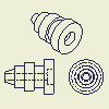
On the Place Views tab, Create panel, use commands to place independent views in single multiview or isometric projections or place a view that captures the current orientation of the model. |
Highlights:
- To begin, create a base view of a model.
- Default settings and values in the Drawing View dialog box are defined in the current standard and can be changed by using Style and Standard Editor.
- Projected views are generally the first type of view created from a base view. The projected view command creates orthographic and isometric views from a base view. You can create multiple views with a single activation of the command.
- You can create a view of a model that contains only sketches. The sketch must be parallel to the drawing view.
- You cannot create additional views from a sketch created in the drawing.
- If you create a view of a part file that contains only surfaces, any surface that is set to Invisible in the part file, does not display in a drawing view. Only surfaces that are set to Visible display in the drawing view.
- After view creation, any surfaces in the corresponding part file that are set to Invisible no longer display in the drawing file.
- If the Enable Background Updates application option is selected, raster views are displayed until calculation of precise views is complete. For more information, see Work with raster views.
Types of drawing views
- Base view: the first view you create. Other views are derived from this view.
- Projected view: an orthographic or isometric view that is generated from the base view or any other existing view.
- Auxiliary view: a view that is projected perpendicular to a selected edge or line.
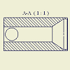
- Section view: a view created by sketching a line that defines a plane used to cut through a part or assembly. The view represents the surface area of the cut.
- Detail view: an enlarged view of a portion of another drawing view. Detail views are used to provide clearer, more precise annotation.
- Overlay view: a single view created from multiple positional representations. Overlay views show an assembly in various positions.
- Draft view: a view that contains one or more associated 2D sketches. It is not created from a 3D part.
Drawing view operations
- Break: an operation which reduces the size of a longer model by removing or "breaking" irrelevant portions. Dimensions that span the break reflect the correct length.
- Break Out: an operation that removes a defined area of material to expose obscured parts or features in an existing drawing view.
- Crop: an operation that provides control over the view boundary in an existing drawing view.
- Slice: an operation that produces a zero-depth section from an existing drawing view.
View Styles
Use Style and Standard Editor to set up the default properties of drawing views and view annotations.
The Standard style controls the view label defaults, display of threads, and projection type. To change the settings, click
Manage tab
 Styles and Standards panel
 Styles Editor
then click the View Preference tab in the Standard panel.
When a section, detail, or auxiliary view is created, alphanumeric auto-indexing is used to generate the view identifier. The following characters are excluded from the indexing sequence by default: I, O, Q, S, X, and Z. You can customize the list of excluded characters on the General tab of the Standard Style panel.
The View Annotation style controls the text style for view labels and defaults for view annotation lines and arrows. To change the style, expand the View Annotation item in Style and Standard Editor, and select a View Annotation style from the list. Then edit the style and save the changes.
Right-click and use the editing commands to override the appearance of view annotations in the drawing.
View scales
When you place the first drawing view, Autodesk Inventor uses the sheet size and the overall size of the model to determine a reasonable view scale. The first view sets the default scale for subsequent views. You can accept the default scale or set a different scale.
If you change the view scale, the scale for dependent views on the same sheet updates as well. You can change the scale of a dependent view independent of its parent view.
The scale for dependent views on a different sheet is not automatically updated when the scale of the parent view changes.
View position on a sheet
To move a view, click and drag the red border. You can move multiple views with a selection window. Click in the upper right corner and drag diagonally from right to left, enclosing the appropriate views in the window, and then click again. Views that are fully or partly within the selection window borders are selected. Click and drag a red border to move the views.
You can also select multiple views by holding down Shift or Ctrl key as you select each view. Remove a view from the selection set by holding down the Shift key and selecting one or more views.
Moving or copying views to other sheets
To move a view to another sheet, drag the view from one sheet to another in the browser.
To copy views, select views in the browser or graphic window, right-click, and click Copy. Then right-click a sheet to place the view copies to, and click Paste.
When documenting large or complex models, it is often necessary to place a dependent view on a different sheet than its parent view. If you place a dependent view on a different sheet, a projection line is placed next to the parent view. In the browser, the dependent view is listed under its parent view with a shortcut icon. To display the dependent view, double-click the shortcut icon. There is also a shortcut to the parent view from the sheet that contains the dependent view.
Working with assembly components in drawing views
You can select individual assembly components in a drawing view and change their line color and line style.
Section views of an assembly
 |
You can create a section view through an entire assembly or exclude components from sectioning. To exclude a component, select the component in the parent view, and then clear the section option before creating the section view. |
Cut inheritance in child views
- Isometric projected views created for section views inherit the section cut by default. Orthographic projected and auxiliary views support the inheritance of the section, but it is switched off by default.
- Isometric projected views created for views with a breakout inherit the breakout cut by default. Orthographic projected and auxiliary views do not support the inheritance of breakout operations.
- For orthographic projection, child views inherit breaks by default if the view projection direction is parallel to break lines.
Suppressed drawing views
You can set the Suppress option for a drawing view to control whether the view is visible or suppressed.
The Suppress option provides a higher level of visibility control, which supplements the visibility control for components, annotations, model edges, and layer visibility. The Suppress attribute affects all model-generated geometry (visible and hidden edges, thread edges, tweak trails) and annotations attached to the selected view (view sketch, dimensions, symbols, centerlines). View visibility suppression is not provided for overlays and breakouts.
- If a section view is suppressed, section view sketch (profile) is hidden in the parent view.
- Breakouts hide, if the parent view is suppressed.
- Visibility of an overlay view is controlled by its parent view.
Salvaged drawing views
When importing models the data can sometimes be poor. You can create drawing views without cleaning up the data.
|
|
When you create a drawing view for sick imported data, a warning dialog is displayed. If you decide to create a salvaged view, an alternate algorithm for computing is used, and the resulting salvaged view is marked by an icon next to the view node in the browser. The drawing view may not be accurate for the individual sick bodies. You can manually clean the drawing view, or discard it. |
Views of sketches
You can create views of parts that contain only 2D or 3D sketches, but no solid bodies. 2D sketches are visible only in base views and must be parallel to the view.
Views of surfaces
When you create a view of a part file that contains only surfaces, any surface that is set to Invisible in the part file, do not display in a drawing view. Only surfaces that are set to Visible displays in the drawing view.
After view creation, any surfaces in the corresponding part file that are set to Invisible will no longer display in the drawing file.
Views of sheet metal parts or iParts
To create a base view of a sheet metal model, click
Place Views tab
 Create panel
 Base
on the ribbon. Then select the sheet metal file and set appropriate options on the Drawing View dialog box.
Two types of drawing views can be created for a sheet metal part or iPart: Folded model view and flat pattern view. The Flat Pattern option is available only if a flat pattern exists in the source file.
Highlights (Sheet Metal iParts):
- When you create a drawing view for a sheet metal iPart, you can select an explicit iPart member on the Model State tab of the Drawing View dialog box.
- If a flat pattern is available in an iPart member file, the Flat Pattern option is enabled in the Drawing View dialog box.
- To update an out-of-date iPart member, select the member on the Model State tab of the Drawing View dialog box.
- To reference a specific iPart member instead of Active Factory Member in a legacy drawing, edit the drawing view and select the member on the Model State tab of the Drawing View dialog box.
Exploded views
Exploded views and other presentation views are developed in a separate file called a presentation file.
A presentation file can contain as many views of an assembly as needed. Set up the presentation views with the appropriate orientation, visibility, and explosion layout. When you add a presentation view to drawing, you specify the presentation file and view to use.
Splines in drawing views
When you generate drawing views of models with spline geometry, now real spline curves are used in drawings.
The real spline geometry is used for newly created splines only.