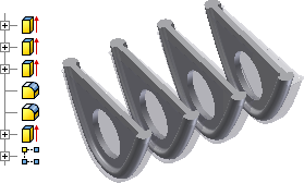
- Turn on the visibility of the composite repair body with errors and compare the new feature to the existing repair body feature.

- If necessary, turn off the visibility of the table top and stand in the Solid Bodies folder.
 Click the Rectangular Pattern command.
 - Select all features associated with the mounting tab.
- Click Direction 1 and then click the Y Axis in the Origin folder.
- Set the count to 4 and the column spacing to 1.3. Click OK to create the pattern. The patterned shapes and spacing are similar to the original design in the repair body.

 Click the Mirror command.
 - Select the rectangular pattern as the feature to mirror.
- Select the YZ Plane in the Origin folder as the Mirror Plane and then click OK.
- Click the Mirror command again.
- Select the first mirrored feature set as the feature to mirror.
- Select the XZ Plane in the Origin folder as the Mirror Plane and then click OK.