 Click the Home view.
 - In the Origins folder, right-click the XZ plane and turn on the visibility.
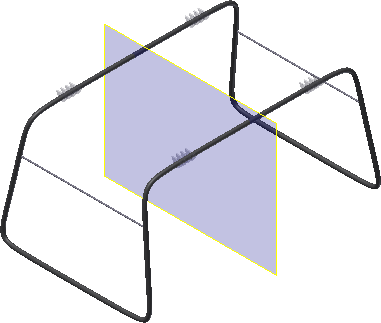
- In the Solid Bodies folder, right-click the stand and turn off the visibility.
 Click the work plane command.
 - Left-click an edge of the XZ plane and hold the left mouse button down while you drag the new plane in the negative Y direction. Enter an offset distance of -21.5 and accept.
- Click the edge of the offset work plane and choose Flip Normal in the context menu to redefine the positive Z face. Notice the color change.
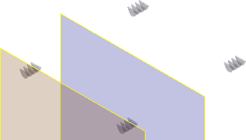
 Click an edge of the offset work plane and start a new 2D Sketch.
 - Turn off the visibility of the XZ plane and the Work Plane.
- Click the Left view on the View Cube and then zoom in on the upper left corner.
- Draw a horizontal line that approximates the width of the mounting tab.

- In the browser, expand the repair node and turn off the visibility of the composite surface.
- Create three arcs as shown in the following image and add the constraints listed. Your sketch can be slightly different until dimensions are added.
- A Horizontal constraint on the line.
- A Tangent constraint between the arc segments.
- A Vertical constraint between the center point of the middle arc and the midpoint of the horizontal line.
- An Equal constraint on the two side arcs.
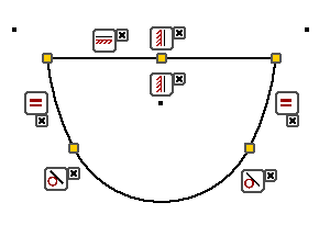
Notice that the center points of the two equal arcs are outside the shape and above the horizontal line. After you add constraints, drag one of the arc centers to match the image.
- Add the dimensions shown in the following image to fully constrain the sketch. Note: The 35.063 and 17.400 dimensions are attached to the projected origin center point. If you did not enable Autoproject part origin in the Application Options Sketch tab, manually project the Center Point to locate these dimensions.Important: Add the 2.5-inch vertical dimension after you add the 7.135 radial dimension.

- Finish the sketch.
- Click the Extrude command. Set the distance to 0.4.
 In the mini-toolbar or the dialog box and select New Solid.
 - Flip the direction to match the following image.
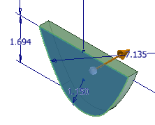
- Click OK to create the extrusion.
- Start a new sketch on the face shown in the following image.
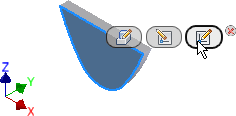
 Start the Offset command, right-click, and disable Loop Select. Verify that Constrain Offset is enabled. Note: When you change an offset setting, it is persistent between sessions. It remains in the state you selected until you change the setting.
- Select the three arc segments, right-click, and choose Continue.
- Drag the offset to the inside and left-click to place.
 Start the Trim command and trim the arcs to the intersection with the horizontal line.
 - Add two tangent constraints between the arc segments.
- Start the Dimension command and add a 0.25 dimension as shown in the following image.
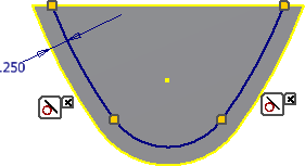
- Finish the sketch.
- Start the Extrude command, select the inside shape, and extrude with a cut a distance of 0.125.
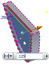
- Start a new sketch on the opposite face, and repeat steps 20 - 27. When you finish, the feature should match the following image.

- Start the Fillet command and add a 0.20 fillet to the two outside edges.
- Add a 0.05 fillet to the four inside edges.
- Start the Hole command and create a 1.25 diameter concentric hole, Through All.
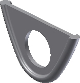
The tab design is complete.