Find Errors
Use the Find Errors command to check the body for quality and serious errors. If errors are found, the Heal Errors command is enabled.
- In the part browser, double-click the repair node to enter the repair environment. Alternatively, you can right-click the repair node and select Repair Bodies.
- Select solids or surfaces to examine, using one of the following methods:
- On the ribbon, click
Repair tab
 Repair panel
Find Errors
. Note: "Bodies" refers to solids and surfaces.
Repair panel
Find Errors
. Note: "Bodies" refers to solids and surfaces. - In the browser, right-click a body and select Find Errors.
- On the ribbon, click
Repair tab
- In the browser or graphics screen, select bodies to check, or choose Select All.
- Select OK to check the data.
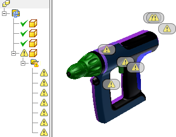
- If errors are detected, they are listed by type in the browser.
- Click an error in the browser to show the error location glyph in the graphics window.
- Click an error glyph in the graphics window to start the error repair mini-toolbar.
Geometry errors can cause downstream modeling operations to fail or prevent the bodies from being solidified. Find Errors lists curves, bodies or surfaces with geometry errors and groups them by error type in the browser. Use Heal Errors before you repair topology errors.
Geometry errors
|
Error types |
|
|
Self-intersecting surfaces |
A surface that folds onto itself is a self-intersecting surface. Surfaces must be continuous and smooth without changing direction. |
|
Self-intersecting curves |
Curve data comprises lines, arcs, or splines. Curves must be smooth without changing direction. Curves cannot reverse, twist, or intersect. |
|
Modeling Uncertainty |
The bodies or surfaces have low level errors. |
|
Overlapping Faces |
Two or more faces are coplanar or overlay each other. |
|
Intersecting Faces |
Two or more faces converge or pass through one another. |
|
Irregular Surfaces |
The generated surface that was approximated during translation did not fit within system tolerances of the original surface in the imported file. Or, a point on the surface is not pointing in the same direction as the rest of the surface. These errors can occur if surfaces are twisted or collapse into a small area. |
|
Face orientation issues |
The loop direction is inconsistent with the normal direction of the face, or inner loops do not agree with each other. The top side of a face is referred to as the surface normal. Adjacent faces within a solid must all have a consistent normal direction. For example, the normal direction of the faces of a box must all point either inward or outward to be a valid solid. |
|
Loop orientation issues |
The outer loop is going in a wrong direction compared to the face normal direction. If the face includes islands (loops enclosed within the outer loop), the normal direction of the islands must point opposite to the outer loop. Loop direction is defined by the start and endpoint and direction indicator. In addition to the loop and islands having the same direction, a surface has a normal direction that must agree with the loop direction. If any of the directions are opposite the others, an error occurs. |
|
Duplicate vertices |
Start and endpoints of an edge are vertices. During translation, attempts are made to merge vertices that fall within the system tolerances. Duplicate vertices can occur when extremely small edges make up a complex object. |
|
Irregular Curve |
Math data is inconsistent in the curve definition or a vector is zero. This error can occur when the approximating surface does not fit within the system tolerance of the defining surface in the neutral file. |
|
Singularity surface |
A point on the surface vector is poorly defined. The surface normal cannot be determined. |
|
Degenerate surface |
The points that comprise the surface are in an area that is too small. |
|
Surface discontinuities |
The normal direction or curvature of the surface changed abruptly. The error may be caused by disconnected geometry. Surfaces must be smooth and cannot have an abrupt change in direction (G0). |
|
Curve discontinuities |
Curve data comprises lines, arcs, or splines. Curves must be smooth without abruptly changing direction (G0) and cannot have an abrupt transition between curves. |