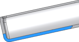
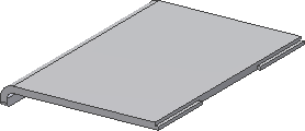
Orient the view to match the following image. We will use the Lip command to create a lip-groove combination on one side of the battery cover limited by two planes.
- Create two work planes parallel to the planar side faces of the battery cover offset -15 mm to the inside.
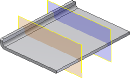
- Click the Lip command.
- On the Shape tab, make sure the Lip button is selected.
- Select the internal edges on the far side of the curve as the Path Edges.
- Select the Guide Face option, and pick the planar face next to the selected edge.
- Leave the Pull Direction unchecked.
- Check the Path Extents box, and select the two planes.
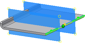
The preview shows the portions of the Lip that are selected (first and last). If the preview matches the following image, the selection is correct. If it does not match the preview, click the green and yellow dots to change the selection.
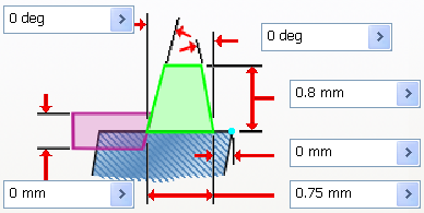
- On the Lip tab:
- For Outside Angle, enter 0 deg.
- For Inside Angle, enter 0 deg.
- For Height, enter 0.8 mm.
- For Shoulder Width, enter 0 mm.
- For Width, enter 0.75 mm.
- For Clearance, enter 0 mm.
- Click OK to create the lip.
The work planes are not shown in the following image. Leave the visibility of the work planes on to create the mating lip feature on the bottom body.
- Turn off the Visibility of the battery cover, and turn on the Visibility of the bottom body.
We will now create the mating groove for the battery cover on the bottom body.
- Click the Lip command.
- On the Shape tab, click Groove.
- Select the inside edge as the Path Edges.
- Select the Guide Face, and pick the planar face next to the edge.
- Leave the Pull Direction box blank.
- Click the Path Extents check box and select the two limiting planes. The default selection of the two outer groove segments is correct.
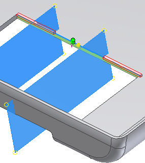
- On the Groove tab:
- For Outside Angle, enter 0 deg.
- For Inside Angle, enter 0 deg.
- For Height, enter 0.8 mm.
- For Shoulder Width, enter 0 mm.
- For Width, enter 0.75 mm.
- For Clearance, enter 0 mm.
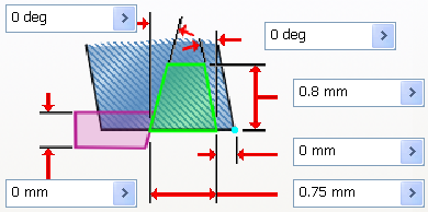
- Click OK to create the groove feature. Turn off the Visibility of the work planes.
The following image shows the lip and groove features in a cutaway view of the battery cover and the lower body.
