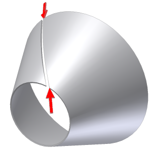
Use the Rip command to create a gap in a sheet metal part created using closed profile sketches to allow flattening. The Point to Point Rip Type requires selection of a model face and two existing points to define the Rip begin and end locations. As with the single point Rip type, the points you select may be work points, midpoints on edges, endpoints on face vertices, or sketched points from a previously created sketch.
- On the ribbon, click
Sheet Metal tab
 Modify panel
 Rip
.
Rip
. - On the Rip dialog box, select Point to Point from the Rip Type drop-down.
- In the graphics window, select the face of the sheet metal model to rip.
- In the graphics window, select the point that defines the rip begin location.
- In the graphics window, select the point that defines the rip end location.
- On the Rip dialog box, optionally enter a value that differs from GapSize for the Rip Gap Value.
- On the Rip dialog box, optionally specify the Rip gap to be on the selected point or offset to the right or left.
- Click OK to create the Rip and close the dialog box. Optionally, click Apply to create the Rip and leave the dialog box open to create additional Rip features.
Note: Click Cancel at anytime to discard any input and close the dialog box.