Enables you to maintain a library of styles used to control the population of routes and runs. This includes the ability to add and import new styles, and modify, copy, view, export, and delete existing styles.
| Access: |
Access the Tube & Pipe Styles command in one of the following ways:
|
The tube and pipe styles editor consists of 3 main areas: the toolbar, the browser, and the tabs. The commands available on the toolbar vary depending on what is selected in the browser.
|
|
Clears the values on the tabs for you to define and save a new style and add it to the local runs template. |
|
|
Enables you to change the settings associated with the selected style definition. |
|
|
Makes a duplicate of the selected style definition and adds it to the list of style definitions. |
|
|
Removes the selected style definition from the local runs template. |
|
|
Imports data for one or more style definitions into the open template. The default template is the local runs template. In the Import dialog box, select an xml file for import. Click OK to import the data. |
|
|
Exports data from the local runs template as an xml file for one or more style definitions selected in the list. You can export entire categories, multiple individual style definitions from one or several categories of the same or different style types. In the Export Tube & Pipe Style dialog box, name the xml file for export. Click OK to export the data. Note: File names entered in the dialog box are saved for the next export.
|
Active Style
Displays the style used when automatically creating a tube or pipe route and when populating a route with library content. To change the active style from the style editor, right-click an individual style in the browser, and select Active.
List of style types, categories, and definitions
Displays the list of available style types. By default, the browser is expanded to the location of the active style, which is displayed in bold text. You can expand the list to view other categories and individual style definitions. Styles without a category appear below the list of categories. Select an individual style, to view or set the values for that definition. You can also select multiple style types, categories, and definitions.
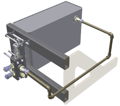
- Rigid Pipe with Fittings creates a series of rigid pipe segments connected with the specified fittings or gaps for groove welds. Fittings can include elbows, couplings, flanges, or gaskets, depending on the style type.

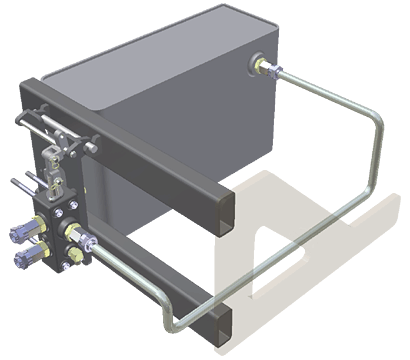
- Tubing with Bends creates a single tube segment that can be straight or with one or more bends.

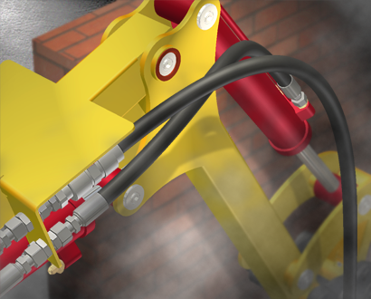
- Flexible Hose creates a flexible hose segment that is typically terminated with a fitting connection on both ends. One or both fitting connections can be suppressed.

General tab
Sets or displays the parameters that determine the style characteristics to use to create the run. The options vary depending on the selected style definition.
|
Name |
Sets or displays the unique name of the selected style definition. This is the name that is displayed in the style browser. |
|
Category |
Optionally, sets or displays the category in which the style definition is organized. Click the arrow to select a different category from the list or specify a unique category. The new category is added to the style browser in alphabetical order. |
|
Butt Welded |
For Rigid Pipe with Fittings style types, sets or displays whether the fittings and pipe segments in the style are butt welded. When enabled, unnecessary parts, such as couplings, are removed from the components list and additional settings regarding gaps are added to the Rules tab. When the style type is both butt welded and flanged, the fitting connections are determined by the end treatment that is set for the fitting. All other end treatment types use a gap to join pipe segments. An additional option is added to the Rules tab to determine the population at the coupling point. |
|
Self Draining |
For Rigid Pipe with Fittings style types, sets or displays whether the fittings and pipe segments in the style are self draining. When enabled, the Elbow Custom selection is added to the Components table. The style can use elbows and tees with custom angles that were previously created and published to the Content Center. A self draining style allows Route and Auto-Route to use the angle defined by the custom elbow. |
|
Flanged |
For Rigid Pipe with Fittings style types, sets or displays whether the fittings and pipe segments in the style are connected to the pipe segments using a flange and a gasket. When enabled, flange and gasket parts are added to the components list and couplings are removed. When the style type is both butt welded and flanged, the fitting connections are determined by the end treatment that is set for the fitting. All other end treatment types use a gap to join pipe segments. An additional option is added to the Rules tab to determine the population at the coupling point. If a Flanged style is selected, Mixed Units are enabled as a style choice for the end treatment. |
|
Mixed Units |
For Rigid Pipe with Fittings Flanged style types, indicates whether the style contains flanged fittings that use mixed units (English units and metric units). When enabled, you must select a flanged fitting that determines the mixed unit diameters to use in the style. |
|
Components |
Sets the fittings and other components to use at connections when creating a tube and pipe run. It also displays the status of the selected component. The available components are dependent on the type of style being created. Double-click a row in any column to select from a list of library parts that meet the style criteria you have set. Right-click a row in any column to select from a context menu. Tip: Pause the cursor over the status symbols to display an explanation for the status.
Fitting specifies or displays the type of tube and pipe fitting to use at connections. A default part is set for each fitting type. The available fitting options are dependent on the type of style being created. Note: Couplings are not required for flanged or welded styles. Flanged fittings are required for a flanged style, with the exception of pipes that include a flanged end. In this case, the flange is not required. Only two-connection fittings are valid for flexible hose styles.
Family the name of the family for the selected fitting. Standard the industry standard used for the selected fitting. The standard determines required attributes for catalog parts. |
|
Use Subassembly |
For flexible hose type styles, sets or displays whether flexible hose components are placed in a subassembly or a flat structure. In a flat structure the parts are listed at the same level as other route components.
|
|
Diameter |
Sets or displays the family member to use for segments in rigid and flexible routes and runs based on size. Click the arrow to select from the list. Nominal sets the nominal diameter values and schedule to use for rigid and bent tube routes and runs. Available schedules are based on the selected nominal diameter. To set the nominal value, click the arrow to select from the list. To select a schedule, click the arrow, and then select from the list. If no schedule is available, you can also use the inside diameter value. Note: When defining a custom part with a given nominal diameter, the nominal diameter must exist as a row in the published iPart table.
OD/ID sets the values for the outside (OD) and inside (ID) diameters for pipe and tube segments. Available IDs are based on the selected OD. Click the arrow to select from the list. |
|
Component Appearance |
Sets the display appearance for all tube and pipe run components. Click the down arrow to display the list of available appearances, and then select from the list. |
|
Custom Elbow Angle |
Available for self draining styles. Sets the filter or displays the slope angle value for a custom elbow. If you specify a previously published custom elbow in the Fittings field, this box is automatically populated with the read-only angle value of the fitting. If the custom elbow was not specified, enter the angle to set the filter value for the fitting. If you do not know the angle, select the calculator icon |
Rules tab
Sets parameters that determine how to create segments of rigid pipe, bent tubing, or flexible hose that run between identified points of the route. The options vary depending on the selected style definition.
|
Segment Length |
Sets the minimum and maximum cut lengths. Minimum the minimum setting for the cut length of a segment. Everything shorter than the minimum setting is considered custom. Maximum the maximum setting for the cut length of a segment. A coupling, flange, or gap for weld grooves is added at the stock length for all segments that are longer than the maximum setting. Increment the increment round-off or cut-off value by which the pipe is adjusted to satisfy the minimum and maximum constraints. Gap sets or displays the distance between pipe segments and pipe segments and fittings for butt welded style definitions. Display Gap sets or displays whether to show the gap upon route and drawing creation for butt welded style definitions Note: The gap is provided for visualization purposes only, it does not affect the length of the pipe. The length of the pipe includes the computation for the gap even if the gap is not displayed. This information is also included when using ISOGEN output.
Bend Radius for bent tubing and flexible hose route types, sets or displays the default bend radius. Overrides can be applied locally for each bend. Hose Round Up Value for flexible hose route types, sets or displays the round up value which is applied to the actual length of the hose. Minimum Bend Radius for flexible hose route types, sets the smallest bend radius allowed for the hose segment. |
|
Coupling Type |
Use Flanges for Couplings indicates whether to use a gap or flange to join pipe segments for styles that are both butt welded and flanged. Enable the check box to use flanges. Clear the check box to use gaps. All other end treatment types use a gap to join pipe segments. |
Browser context menu
Right-click a node in the Tube & Pipe Styles browser to display a context menu. The context menu varies depending on the selected node.
|
Active |
Sets the selected style as active. The active style is used when creating and populating routes and runs. |
|
New |
Clears the values on the tabs for you to define a new style and add it to the local runs template. The exception is Component Appearance, which is set to As Material. |
|
Edit |
Enables you to change the settings associated with the selected style definition. |
|
Copy |
Makes a duplicate of the selected style definition and adds it to the list of style definitions. |
|
Delete |
Removes the selected style definition from the local runs template. |
|
Import |
Imports data for one or more style definitions into the open template. In the Import dialog box, select an xml file for import. Click OK to import the data. |
|
Export |
Exports the selected style definition(s) data from the local runs template as an xml file. You can export entire categories, multiple individual style definitions from one or several categories of the same or different style types. In the Export Tube & Pipe Style dialog box, name the xml file for export. Click OK to export the data. Note: File names entered in the dialog box are saved for the next export.
|
Components list box context menu
Right-click a row in any column of the Components table to display and select from a context menu. The context menu varies depending on the selected row.
|
Browse |
Displays the Library Browser which lists components that meet the current style criteria. You can select from the current list, or set additional filtering before making your selection. |
|
Clear |
Removes all information on components that have been selected from the Components table. |
|
Suppress Fitting |
For flexible hose styles, enables you to suppress or unsuppress start and end fittings. |
