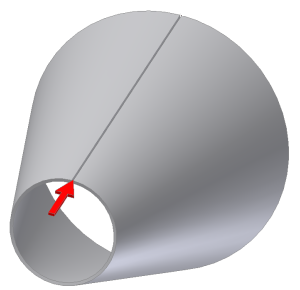
Use the Rip command to create a gap in a sheet metal part created using closed profile sketches to allow flattening. The Single Point Rip Type requires selection of a model face and an existing point to define the Rip location. The point you select may be a work point, a midpoint on an edge, an endpoint on a face vertex, or a sketched point from a previously created sketch.
- On the ribbon, click
Sheet Metal tab
 Modify panel
 Rip
.
Rip
. - On the Rip dialog box, select Single Point from the Rip Type drop-down.
- In the graphics window, select the face of the sheet metal model to rip.
- In the graphics window, select the point that defines the rip location.
- On the Rip dialog box, optionally enter a value that differs from GapSize for the Rip Gap Value.
- Optionally, specify the Rip gap to be on the selected point or offset to the right or left.
- Click OK to create the Rip and close the dialog box. Optionally, click Apply to create the Rip and leave the dialog box open to create additional Rip features.
Note: Click Cancel at anytime to discard any input and close the dialog box.