In this section, you create a cooling channel for the mold design.
The cooling channel circulates a coolant through the mold to cool down the mold quickly and uniformly.
- On the ribbon, click Mold Layout tab > Runners and Channels panel > Cooling Channel
 .
. - In the upper-right corner of the graphics window, click Right on the ViewCube to orient the model.
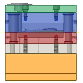
- Activate the Face selection tool. Select the location shown in the following image.
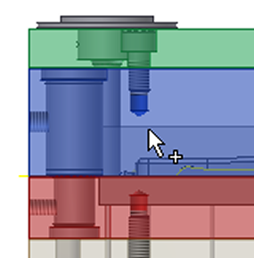
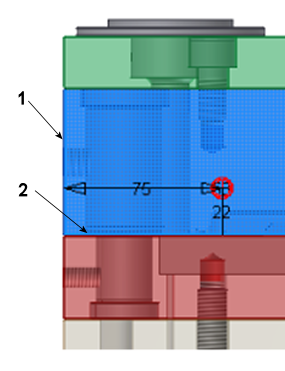
- Select the edge identified as 1 (outside of chamfer) in the following image as the Linear Edge 1 reference.
- Select the edge identified as 2 (chamfer) in the following image as the Linear Edge 2 reference.
- Edit the X and Y axis locations as follows:
- Distance from Linear Edge 1 = 75 mm.
- Distance from Linear Edge 2 = 22 mm.
- From the Extents List on the Cooling Channel dialog box, select Through All.
- Click the Symmetrical check box.
- Click Apply.
- Click OK to accept the defaults on the file naming dialog box. The cooling channel appears as shown in the following image.
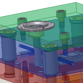
- Repeat steps 3 through 10 to create three more cooling channels, as shown in the following image.
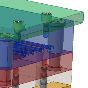
- The distances from Linear Edge 1 and 2 for each of the cooling channels are listed in the following table. Make sure that you select the outside edges and not the chamfered edges.
Cooling Channel Distance from Linear Edge 1 Distance from Linear Edge 2 Cooling Channel 2 105 mm 22 mm Cooling Channel 3 135 mm 22 mm Cooling Channel 4 170 mm 22 mm - Click Apply to create each cooling channel. After all four cooling channels have been created, click Done on the Cooling Channel dialog box.