In this section, you define the location of the gate.
Gate locations are coordinates on the surface of a moldable part, which indicate where the physical gates will be placed. Up to ten gate locations can exist on a part, and they can be established manually or the Inventor Mold Design application can suggest them. You run a Gate Location simulation, which is used to recommend injection locations for the part, based on minimizing the flow resistance.
- On the ribbon, click Mold Layout tab > Runners and Channels panel > Gate Location
 .
. - In the Gate Location dialog box, select the Suggest tab.
- In the Number of Gate Locations [1:10] field, maintain the default 1 ul value to suggest a single gate.
- Click Start on the Gate Location dialog box.
- Read the Analysis running dialog box and click OK. You can stop the simulation at any time by clicking Stop on the Gate Location dialog box.
- While the simulation is still running, on the ribbon, click Mold Layout tab > Tools panel > Job Manager
 . Note: When you first open it, the Job Manager dialog box indicates that no simulations are running. It takes time for the list to update and the Gate Location simulation to appear.
 - The Job Manager dialog box enables you to monitor the progress and stop it, if necessary. You can close the Job Manager dialog box without stopping the simulation, but for now, keep this dialog box open until the simulation has finished.
- The Summary dialog box appears when the simulation has finished. Select the Gate Location tab, which contains the recommended location of the gate.
- Click OK on the Summary dialog box.
- Click OK on the File Naming dialog box to accept the defaults.
- Inventor Mold Design generates the Gate Location, which is based on the simulation results, and closes the dialog box.
- On the Mold Design browser, expand the MobileTopComplete > Gate Locations nodes. Right-click Gate Location 1 and click Edit Feature.
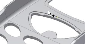
- Rotate the model and zoom into the point. Notice the location of the system-generated gate location.
The simulation result is only a suggestion for the optimal region. The final gate location is a compromise based on part use, appearance, and tooling restrictions. In this situation, the suggested gate location is on a thin feature. It is not ideal because it makes it difficult to pack out the part. You now modify the reference surface and values to reposition the gate point. The new gate point is close to the suggested location, and is on the nominal wall of the part and on the underside of the model. Placing the gate location on the top of the model would be unsuitable because it could leave a witness mark.
- Click Location
 on the Gate Location dialog box, and select the surface shown in the following image.
- Change the gate location by modifying the following parameters:
- U = 0.5
- V = 0.525
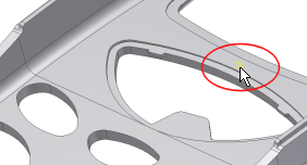
- Click OK on the Gate Location dialog box. The gate location updates, as shown in the following image.

When using the simulation tools in Inventor Mold Design, an AIT directory is created in Windows Explorer. This directory is located in the mold design directory in which you are working, and contains the simulation data and results files. The AIT directory is generated when running simulations. These files are considered as part of your design, and will be properly handled by system utilities like Pack & Go and Vault.