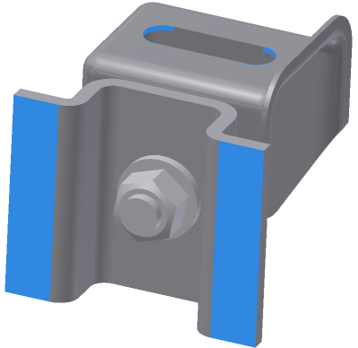
Add a structural (![]() fixed,
fixed, ![]() frictionless, or
frictionless, or ![]() pin) constraint:
pin) constraint:
- On the ribbon, click the constraint command for the type of constraint to add.Note: You can also right-click the Constraints node
 in the browser and select the appropriate constraint type from the context menu.
 - In the dialog box, the select command is active, so you can immediately select the constraint location. Select the appropriate input for the constraint type. If you select more than one input, the selections must be of the same type: such as face, edge, or vertex. The input type is based on the constraint type.

- Optionally, you can use the
 (More) command to expand the dialog box for access to other constraint parameters. The available parameters are based on the constraint type.
 - Click OK to add the constraint and close the dialog box. Alternatively, click Apply to add the constraint and keep the dialog box open.
You can edit or suppress constraints after you run the simulation, then rerun the simulation and see the effect of changing or suppressing the constraint.
Note: You cannot exclude part-part contact areas from constraints applied to faces containing the contact. Avoid applying improper constraints to contacting faces.
Apply a fixed constraint with non-zero displacement
- In the Fixed Constraint dialog box, click the
 (More) button. The dialog box expands to provide access to additional settings.
 - Select Use Vector Components.
- Select the x, y, or z vector components appropriate for defining your displacement vector.
- Enter the appropriate displacement magnitudes for each vector component.
- Click OK to apply the constraint.
You can apply a displacement in addition to a fixed constraint. To specify the displacement, do the following: