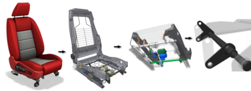
When considering a part or assembly for analysis, there are considerations worth making. Among them is model preparation. To prepare an assembly model for analysis, evaluate the types of components. In a part model, evaluate the part features. Then you can remove low impact parts or features from the analysis, and improve performance with relatively little difference in the analysis result.
The actions that prepare a part or assembly for analysis are:
Simplify the model
Why simplify an assembly?
When you analyze assemblies, you can exclude small parts whose functionality is simulated by constraints or forces. Simplifying an assembly, where possible, helps reduce simulation times.
Why simplify part features?
When you conduct simulation analyses, you can tailor portions of a model to allow for a more efficient analysis. This tailoring involves suppressing geometrically small features that are not subject to stress concentrations. An example is outer convex rounds. They can complicate mesh creation, without significant effects to the final result.
Why simplify your model containing thin bodies?
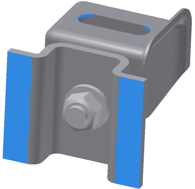
Your model can often contain components that are comprised of very thin wall bodies relative to the overall dimensions or size of the model, so can be very thin (for example sheet metal or frame structures). Therefore an analysis of such components using solid elements based FEA demands large computational resources and it can provide less accurate results. When you simplify components containing thin wall bodies to shells you may dramatically reduce computational resources required as well as increase precision of your simulation.
You may inspect your model to see if there are thin bodies which are good candidates for shell feature by clicking the Find Thin Bodies command on the Prepare panel.
Bodies that meet the thin component criteria are found within your model automatically. Then you can decide to simplify the solid geometry and generate mid-surfaces defining shell structure using Midsurface command or Offset command.
What are the limits for using the thin parts commands in Stress Analysis?
L/D ratio = Length /Thickness
where:
Length = overall length of the body
Thickness = thickness of the body
Consider a thin square plate whose length and width are 100 with a thickness of 1. The L/D ratio of such a plate is 100/1 = 100. We compute the L/D ratio of the input body and compare it with the thin square plate’s L/D ratio.
- If the L/D ratio is below 100, the body is considered as thick (or solid), and we recommend to analyze it as solid to perform accurate analysis using solid elements.
- If the L/D ratio of the input body is above 100, then the body is considered as a thin component, and is highlighted as such after you click the Find Thin Bodies command.
- If the L/D ratio is above 100 and you perform the analysis without converting them to a Shell using either Midsurface or, Offset, a message displays recommending using the Find Thin Bodies command to perform more accurate analysis.
- If the L/D ratio is above 250, and the body is being analyzed as a thick solid, a warning message displays indicating that results of analysis are very likely to be inaccurate and not precise.
Add Constraints

Structural constraints restrict or limit the displacement of the model. For static simulations, remove all rigid body modes (free translational and rotational movement of the bodies). To do so, fix a face, for example, or combine partial constraints on faces, edges, or vertices.
Types of structural constraints are:
| Fixed |
Removes all degrees of freedom. |
| Frictionless |
Prevents movement normal to the surface. |
| Pin | Isolates degrees of freedom to radial, axial, or tangential. |
To display the reaction force information, run the simulation and then right-click a constraint in the Simulation browser, select Reaction Forces.
Add Loads
Structural loads
Structural loads are forces applied to a part or assembly during operation. Such loads cause stresses, deformations, and displacements in components.
In product design, it is important to know how your product reacts under normal and excessive working conditions. Know how to determine the response your product has to these loads, and build in an appropriate safety factor. Important aspects of your design include load magnitude, frequency of occurrence, distribution, and nature (static or dynamic). If you can visualize how your product responds to loads, you can control your designs better.
The types of structural loads available are:
- Force (N or lbforce)
- Pressure (MPa or psi)
- Bearing Load (N or lbforce)
- Moment (N*m or lbforce in)
- Remote Force (N or lb)
Apply structural loads Normal to the face where the force is perpendicular to the face. Apply structural loads Directional to the face with a magnitude specified in each direction. You can apply moments to solid faces. Use remote force to:
- Apply a force at a specific point outside or inside of the model.
- Be transformed as an equivalent force and moment on a given face.
You can apply Bearing load to cylindrical faces only.
Body loads
A body load is a load acting on the entire volume or mass of a component. Examples of body loads include, but are not limited to:
- Gravitational force
- Linear acceleration
- Angular velocity and acceleration
Body loads created through the application of:
If the model experiences the effect of outside forces, define gravitational or body loads. You can define up to one gravitational and one body load per simulation.
Specify Materials
Material properties define the structural characteristics of each part of a model for a simulation. Each simulation can have a different set of materials for any component.
Styles and Standards
The Inventor materials are managed with the Styles and Standards Editor. You can modify existing materials or create new ones. When you create or modify materials, be careful to assign the correct material characteristics.
Material definitions
When a new part is started, the component material is set to whatever the document template uses. With Inventor, as shipped, the document templates for part and assembly use a material called Default. The Default material is not defined for use in the simulation environment. As a result, if the material for any component is assigned the Default, override the material. There are several ways to correct the material assignment:
- Edit the part. In the iProperties, specify a material that is properly defined for simulation use. This solution is the recommended.
- Override the Inventor default material with another properly defined material.
- Modify the Default material to make it usable for simulations. Use caution if you modify the template file to redefine the Default material. Other documents sometimes depend on the original definition.
There are two ways in which a material can be invalid for a simulation.
- The assigned part model material is not fully defined. It is missing critical information to satisfy the simulation requirements. In this case, you receive a warning message about the material. You can override the material with one suited for analysis or modify the existing material before running the simulation.
- The override material is not fully defined. It is missing critical information to satisfy the simulation requirements. The override material node in the browser is decorated with the information
 icon. You can override the material with one suited for analysis or modify the existing material before running the simulation.
Simulation Browser
In the simulation browser, there is a Materials folder ![]() in which you find a list of all materials that override other materials. For example, if you have a Copper component, and override the Copper with Steel, there is a unique node for Steel. The Steel node contains nodes for each part using that material.
in which you find a list of all materials that override other materials. For example, if you have a Copper component, and override the Copper with Steel, there is a unique node for Steel. The Steel node contains nodes for each part using that material.
The following are assumptions about the behavior of materials:
| Constant | All structural material properties do not change with respect to temperature and time. |
| Homogeneous | Material properties do not change throughout the volume of the part. |
| Linear Structural | Stress is directly proportional to strain. |
If a simulation material is better suited to your design needs, promote the material assignment to the model as a CAD edit.
Specify Contact Conditions
There are two methods for adding contact conditions to the simulation:
| Automatic Contacts | Software assigned contacts based on the settings in the Edit Simulation Properties dialog box. Automatic contacts can be edited at any time in the process. |
| Manual Contact | Contacts you assign through use of the command. Manual contacts can be edited at any time in the process. |
Other considerations:
Warning icons at parent browser nodes
State icons display next to parent nodes in the Stress Analysis browser to indicate a node is out-of-date, or issues exist for the child nodes. Initially, the Update Required icon ![]() displays next to the parent node. If the Warning icon
displays next to the parent node. If the Warning icon ![]() appears after the node is updated, then an issue exists for one or more child nodes.
appears after the node is updated, then an issue exists for one or more child nodes.