Every part and assembly file contains a coordinate system. The coordinate system is represented by a set of planes, axes, and a point collected into the Origin folder in the browser. By default, this work geometry is not visible, but you can use it for constraints and make it visible.
- Right-click the Origin folder in the browser, and select Expand All Children to see the browser nodes you use to select the origin geometry when it is not displayed.
- On the ribbon, click Sketch tab
 Draw panel Project Geometry.
- Select the browser node Center Point to include the origin point as a point in your sketch.
- Click Sketch tabConstrain panel Coincident Constraint.

- Select the lower endpoint of the left-most line, and then the projected origin point.
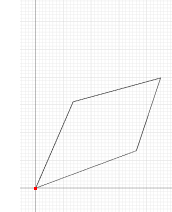
Notice that two line segments adjust their length and angle to allow the endpoint to become coincident with the origin point.
Note: Do not be concerned if the shape of your geometry does not exactly match the illustrations.