In the next portion of the tutorial, you convert the iFeature that you just created to a table-driven iFeature. It will place T Slots of different sizes. You will edit the table definition to contain the various size parameters. You will also add a key to use to select a slot of a certain size during placement.
- Open the file tutorial_TSlot.ide. Note: Because you just saved a file to the Slots folder, that location should be active when you select Open. If it is not, a backup copy of the file can be found at ...\Autodesk\Inventor [Version]\Tutorial Files\iFeatures.
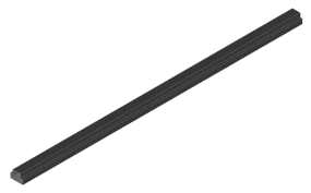
iFeatures are stored in files with an *.IDE file extension. They contain geometry representing the features they will add (or subtract). The tutorial_TSlot file contains black surfaces representing the cut extrude. You do not make any edits to model features using the iFeature Author Table.

The ribbon tab containing the iFeature panel displays.
- On the ribbon, click iFeature tab
 iFeature panel
  iFeature Author Table.
- Right-click the 1 in the cell to the left of the 12-mm parameter in the lower portion of the iFeature Author dialog box. Select Insert Row from the context menu.


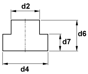
- Set the values of the new row to d2 = 14 mm, d4 = 22 mm, d6 = 16 mm, and d7 = 9 mm.
- Add two additional rows. Set the values for the first row to d2 = 18 mm, d4 = 29 mm, d6 = 19 mm, and d7 = 11 mm. Set the values for the second row to d2 = 22 mm, d4 = 35 mm, d6 = 25 mm, d7 = 14 mm.
The parameter table portion of your dialog box should appear as shown.

- Click the Other tab in the iFeature Author dialog box, and then click on the text Click here to add value.
- In the Name column, click on New Item0 and change the text to Size.
- In the Prompt column, click on Enter New Item0 and change the text to Select size.
- Click the gray key-shaped icon to the left of Size. Notice that the icon changes to blue, and a blue key icon displays in the Size column heading which is now included in the parameter table portion of the dialog box.
- Edit the Size key value for each of the rows in your parameter table as follows:
Value for row 1: M10x1.5 Value for row 2: M12x1.75 Value for row 3: M16x2.0 Value for row 4: M20x2.5 Note: Metric T Nuts are designated by both the slot dimensions and the thread size of the tapped hole. The Size value entered previously is the thread designation for one T Slot size. Not all slot sizes are covered by the values in this tutorial. - Click OK to save the added rows and key column to your iFeature definition.
- Save and close tutorial_TSlot.ide.