In this section, you place two side lock sets. A lock set ensures accurate alignment between the two halves of the mold. The two types of locks sets that can be created are side locks and interlocks.
Side locks are machined on the centerline axis, both vertically and horizontally, on the outside of the mold to ensure alignment of the mold halves. Interlocks also align the mold halves, as well as lock the core and cavities. Interlocks maintain proper alignment while still permitting thermal expansion between the mold halves.
- On the Quick Access toolbar, click Design View > Default.
- On your keyboard, press F6 to return to the Home View.
- On the ribbon, click Mold Assembly tab > Mold Assembly panel > Lock Set
 .
.
- On the Lock Set dialog box, expand the Type menu.
- From the Vendor menu, select DME.
- From the Category menu, select Side Lock.
- From the window, select FW45.
- On the Lock Set dialog box, the Base face
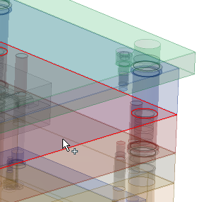
 tool should be active . Select the surface shown in the following image. The base face is the top or bottom surface of one of the mold base plates, which establishes the location of the parting plane.
- On the Lock Set dialog box, the Reference face
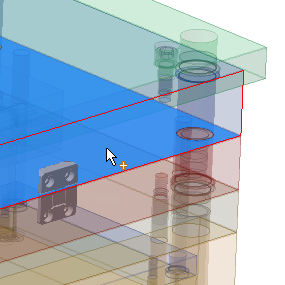
 tool should be active . Select the surface shown in the following image. The reference face on which the side lock will be attached must be perpendicular to the selected base face.
- On the Lock Set dialog box, specify both the distance and the offset as 0mm. The distance represents the measurement between the center of the reference face and the center of the side lock. The offset is the distance into the mold plate that the side lock will be embedded.
- On the Lock Set dialog box, click the Symmetrical Placement option to create a second lock set that is symmetrical with the first lock set. Click OK.
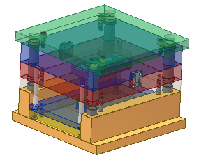
- Click OK on the File Naming dialog box to accept the defaults and place the lock sets. The model appears as shown in the following image.
