Many sheet metal parts are created by bending a portion of the flat sheet. Use the Flange command to add flat material along an edge, portion of an edge or around all edges of a face. The flat material connects to the selected edge using a bend radius defined within your Sheet Metal Rule. The Flange command provides flexibility in the position and size of the flange relative to the selected edge and other features within the evolving model.
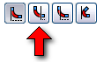
- On the ribbon, click
Sheet Metal tab
 Create panel
Flange
, or right-click and select Flange from the marking menu.
Create panel
Flange
, or right-click and select Flange from the marking menu. - In the graphics window, click to select the three inside edges shown.
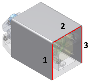
As you select the edges, the Flange feature previews. Note that Flanges created from co-planar edges automatically miter at corners that would otherwise interfere. You can access the Auto-miter option from the Corner tab of the Flange dialog box.
By default, sheet metal Flange features are created using the Bend Position option labeled Inside of bend face extents. This produces a Flange face coincident with the selected edge. In this case, such a Flange would not allow clearance for the corners of Cylinder Base.ipt. Instead, you will change the Bend Position to Bend from the adjacent face, which uses the selected edge as the beginning location of the bend for the Flange.
- Click the Bend Position option labeled Bend from the adjacent face.
 Note: As you click this option, notice that the preview of the three Flange faces moves out from the selected edges. To see this change more clearly, display the model as Wireframe ( View tab
Appearance panel
Wireframe
from under the Visual Style drop-down menu), and view the model from the Top. Switch between Inside of bend face extents and Bend from the adjacent face (be certain to return to Bend from the adjacent face, then reset your display to Shaded and reset your view angle, before continuing).
Note: As you click this option, notice that the preview of the three Flange faces moves out from the selected edges. To see this change more clearly, display the model as Wireframe ( View tab
Appearance panel
Wireframe
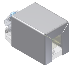
from under the Visual Style drop-down menu), and view the model from the Top. Switch between Inside of bend face extents and Bend from the adjacent face (be certain to return to Bend from the adjacent face, then reset your display to Shaded and reset your view angle, before continuing). - For this Flange feature, use the default value of 90 degrees for the Flange Angle, as well as the default value of 25 mm for the Height Extents Distance.
- Click OK to create the Flange and close the Flange dialog box.
Next, you create a sketch containing center marks for punched holes.