- In the Contour Flange dialog box (in the Width Extents area), click Distance Flip.
- Click > to the right side of the Distance field, and select Measure from the menu.

- With the Measure option active, click in the graphics window to measure the length of the edge shown. Use the measured value as the Distance value for the Contour Flange.

Following the click, the measured value of 120 mm displays in the Distance field and the Contour Flange previews as 120 mm long.
- Click OK to create the displayed Contour Flange and close the dialog box.

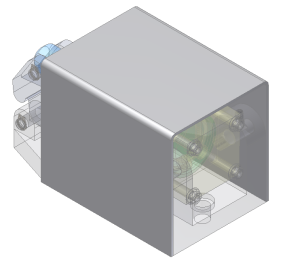
The sheet metal Contour Flange is the base feature in the model file that you created working within the assembly context. The sheet metal part displays as solid while the other components within the assembly display as translucent. By working within the assembly context you were able to use existing critical dimensions without initially knowing their values. Next, you add a sheet metal Flange feature with automatic mitering around three edges along the back side of the guard.