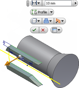
The Extrude command creates a feature by adding depth to an open or closed sketch profile. You specify the direction, depth, taper angle, and termination method for the extrusion.
You now perform an extrude operation with a Cut that uses the two sketch profiles to remove material from the cylindrical portion of the part.
-
 Click Model tab
 Create panel
 Extrude on the ribbon, or press E to invoke the Extrude command. You can also right-click in the graphics window and select Extrude from the marking menu.
 - Select the two sketch profiles.
- After selecting the profiles, the in-canvas display appears in the graphics window. The default option for the Extrude command is to perform a Join operation. The graphical preview appearing on the screen displays in green for a Join.

- Click the flyout arrow on the Operation button and select the Cut option
 .
. - Next, click the flyout arrow on the Direction button and select the Direction 2 option
 , if not already active. Observe that the graphical preview changes color from green to red to indicate a Cut operation. Note also that the gold distance arrow manipulator has reversed position and now points in a negative direction into the screen.
 - Take a moment now and try dragging the distance arrow backward and forward over the object. The red graphical preview shows you the material to be removed during a Cut operation. Note: As an experiment, click the flyout arrow on the Operation button and select the Intersect option
 . An Intersect operation calculates the shared volumes of two or more intersecting objects and graphically previews in blue. After previewing the intersections, click the flyout arrow on the Operation button and select Cut once again.
 - Next, click the flyout arrow on the Extents button
 to display the termination options. Use
 - Distance to extrude a sketch profile with a numeric value which you enter in the value input box. It is the default option.
- To next face/body extrudes to the next part face or solid body encountered in the direction of the extrusion.
- To selected face/point extrudes to an existing part face, work plane, or work point.
- Between two faces/plane selects beginning and ending faces or work planes on which to terminate the extrusion.
- Through All performs a Join, Cut, or Intersect operation through the entire part.
- Now, select the Through All option in the Extents button flyout
 and click the green Ok button to complete the Extrude command.
The new feature, Extrusion1, is added to the Model browser.
