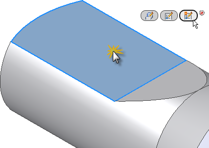
We now create a third sketch to draw and dimension a rectangle. The rectangle is then extruded with a cut to produce a rectangular-shaped opening through the part.
- Click the flattened top face of the part.
- The Direct Manipulation mini-toolbar appears and, starting from the left, displays three buttons offering the following commands:
- Edit Extrude
- Edit Sketch
- Create Sketch
- Select the third button, Create Sketch.

- The view automatically rotates parallel to the XY plane. This is because the Look at sketch plane on sketch creation option on the Sketch tab of the Application Options dialog box is active.
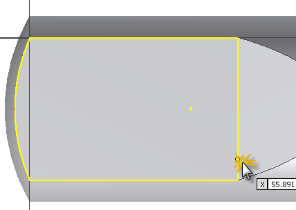
- The edges of the selected face are automatically projected. The Autoproject edges for sketch creation and edit option on the Sketch tab of the Application Options dialog box is also active.
-
 Click Sketch tab
 Draw panel
 Rectangle on the ribbon and select Rectangle Two Point from the drop-down menu. You can also right-click in the graphics window and select Two Point Rectangle from the marking menu.
 - Pick the approximate point shown in the image to place the lower-right corner of the rectangle. Do not be concerned with the values displayed in the Pointer Input fields.
 .
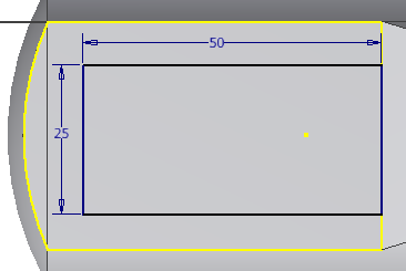
. - Move your cursor to the upper left to activate the rectangle horizontal and vertical value input boxes. The current input focus is in the value input field representing the horizontal dimension. Enter 50 and press Tab. The lock icon indicates that the horizontal dimension of the rectangle is fully constrained.
- Input focus is now shifted to the second value input field representing the vertical dimension. Enter 25 and press Tab.
- Press Enter to draw and dimension the rectangle. The rectangle is fully dimensioned because Dynamic Input with persistent dimensions was used to input the dimensional values.

- Right-click and select Done [Esc] from the marking menu to exit the Two Point Rectangle command. Note: To move a sketch dimension to a new location, select the dimension, and press and hold the left mouse button as you drag the dimension. Release the mouse button when the dimension is placed to your satisfaction.
The new feature, Sketch3, is added to the Model browser.
We now create a single vertical dimension to center the rectangle on the flattened face.
-
 Click Sketch tab
 Constrain panel
 Dimension on the ribbon, or press D to invoke the Dimension command. Remember that you can also select General Dimension from the marking menu.
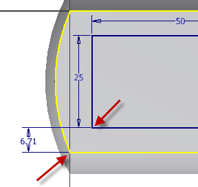
 - Select the two line endpoints shown in the image. Move your cursor to the left and click to place the dimension.
- Enter 6.71 in the Edit Dimension text box. Click the green arrow (or press Enter) to create the dimension.

- Right-click and select Done [Esc] from the marking menu.
-
 Click Sketch tab
 Exit panel
 Finish Sketch on the ribbon, or select Finish Sketch from the marking menu, to finish the sketch and exit the sketch environment.
 - The model rotates automatically into the Home view when you finish the sketch. If not, press function key F6 to rotate the view.