- Set your active project to tutorial_files.
- Use the Open command to select Alias Files (*.wire) from the Files of type drop-down list.
- Navigate to C:\Users\Public\Documents\Autodesk\Inventor [Version]\tutorial files\Keyboard\Original, and select Keyboard.wire from the file list.
- Click Options to display the Alias Import Options dialog box. Make sure that the Associative Import radio button is active.
- Click OK.
- Next, click Open to open the Alias wire file.
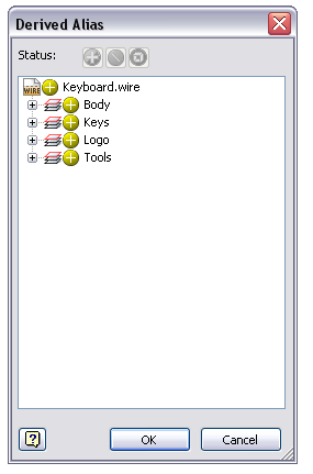
You may experience a slight delay as the wire file is translated directly into Autodesk Inventor and the Derived Alias dialog box displays.

Observe that four node names appear in the dialog box: Body, Keys, Logo, and Tools. The layer icon appears just to the left of the four node names because they represent the layer names of the surfaces which were in Alias.
The top three commands in the Status area at the top of the dialog box remain inactive until you select one of the nodes from the list. Use these commands to select the layer as a composite surface or all surfaces individually. You can also exclude some (or all) surfaces.
Use the + command at the far left to derive all the surfaces as a composite surface. It is the default condition. A composite surface appears in yellow and can be stitched into a solid. Most of the Autodesk Inventor modeling commands, like Shell or Split, can then be performed on the stitched solid.
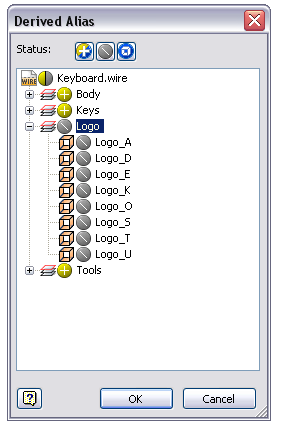
Use the middle command \ to exclude selected surfaces from the yellow composite surface. Excluded surfaces appear translucent.
Use the command at the far right to import objects as individual surfaces. Individual surfaces appear in blue.
- Expand the Logo node to display the eight surfaces that comprise the letters of the Autodesk logo. Click the + command to the left of the logo name. Observe that the icon changes to \ indicating that all eight surfaces are excluded from the composite surface. The logo does not appear in the keyboard model.

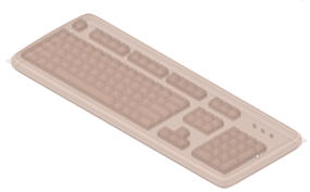
- Click OK to close the dialog box. The translated Alias file now appears in the graphics window as an Autodesk Inventor part file comprised entirely of surface features.

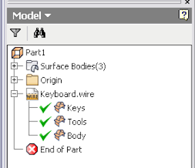
Take a moment now to examine the Model browser. The Keyboard.wire node represents the associative import of the Alias wire file. Expanding the Keyboard.wire node reveals the three composite surface features (Keys, Tools, and Body) that were translated into Autodesk Inventor. The composite names match the native Alias layer names.
 Note: Observe that the Logo surfaces do not appear under the Keyboard.wire node because they were excluded previously in this procedure.
 - Close the file without saving it.