- Use the Open command to select Autodesk Inventor Files (*.iam, *.idw, *.dwg, *.ipt, *.ipn) from the Files of type drop-down list.
- Go up one folder level to C:\Users\Public\Documents\Autodesk\Inventor [Version]\tutorial files\Keyboard, and select Keyboard.ipt from the file list. Click Open to open the part file.
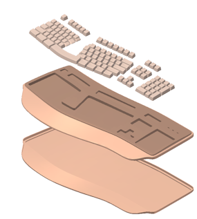
- The completed keyboard part file appears in the graphics window. Rotate the part to view the features.

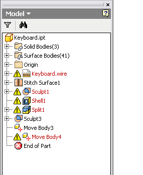
The Model browser lists the operations that were performed on the part file after it was translated into Autodesk Inventor. Observe that the out-of-date icon appears in front of the Keyboard.wire node in the browser.

This icon indicates that the original Alias wire file was edited since it was initially translated into Autodesk Inventor. Now the Autodesk Inventor part file is no longer in sync.
- Click Update on the Quick Access toolbar
 to load the newer version of the Alias file. After a short delay as the wire file loads, the Update Part Document dialog box displays several error messages. Several features that existed in the original Alias wire file are now missing from the revised Alias wire file.
 - Click Accept to close the Update Part Document dialog box.
The Keyboard.wire node appears in a red font in the Model browser indicating that the Alias wire file and the Autodesk Inventor part file are no longer associated correctly.
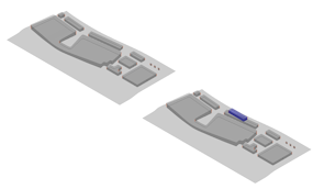
- Right-click the Keyboard.wire node in the Model browser, and select Update Associations from the pop-up context menu. There is a delay while the data is translated. When complete, the Update Associations dialog box appears. Note: Two translucent views now appear in the graphics window. The view on the left contains the information that is in the wire file. The view on the right shows the updated information in Autodesk Inventor.
The Tools layer name appears in the drop-down list at the top of the Update Associations dialog box.
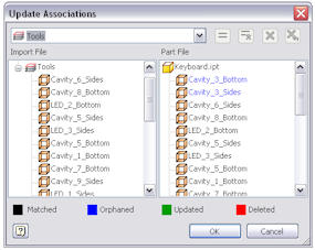
The dialog box has two lists and a color legend that appears below the two lists. Do not be alarmed if the colors in the color legend differ slightly from the colors that appear on your screen. It is because the color legend is based on the Autodesk Inventor color scheme in use.
The list at the left displays the surface names from Alias. The corresponding Autodesk Inventor surface names appear on the right. From left to right, the four status buttons at the bottom are labeled Matched, Orphaned, Updated, and Deleted. Observe from the Keyboard Part File list on the right that surfaces Cavity_3_Bottom and Cavity_3_Sides are orphaned. The two surfaces no longer exist in the Autodesk Inventor part file after the original Alias wire file was edited. Orphaned surface names always appear at the top of the list on the right. These surfaces must be deleted.
Note: There are several ways that you can delete these two surfaces. You can select them individually, or you can hold the Ctrl key and pick them both. Once the surfaces are selected, click the X at the top right of the dialog box to delete. Alternatively, you can right-click and select Delete from the context menu when the surface names are highlighted. - Delete Cavity_3_Bottom and Cavity_3_Sides from the Part File list on the right. The deleted surface names now appear in a different color in the list. You can observe the identical color change in the graphics window.
- Next, select the Body layer from the layer name drop-down list at the top of the dialog box.

Observe that four surfaces from the Alias Body layer are orphaned. In this instance, the surfaces still exist in the two models but they have changed significantly and must be matched.
- To match the orphaned surfaces, select Body_Fillet_A from the Body Import File list on the left. Then, select Body_Fillet_A from the Body Part File list on the right. Now click the Match command = located just to the right of the layer drop-down list. Note: You can also match the two surfaces by right-clicking and selecting Match from the context menu when the surface names are highlighted.
The two surface names in the file lists change color and also appear in this same color in the graphics window.
- Repeat the matching process with Body_Fillet_B and the other two surfaces. Make sure to select = (the Match command) after each pair of surface names are selected from the lists.
- After all four surfaces are matched, click OK to exit the Update Associations dialog box.
There is a slight delay as the associations between the surfaces are updated. When complete, the Autodesk Inventor part file appears in the graphics window reflecting the changes that were made in the edited Alias wire file.
The Update Associations dialog box also appears stating that Stitch Surface4 cannot be built. This error message appears because the two surfaces that were used to create Stitch Surface4 (Cavity_3_Bottom and Cavity_3_Sides) were deleted.
- Click Accept to close the Update Associations dialog box.
- Expand the Sculpt1 node in the Model browser and observe the icon next to Stitch Surface4.
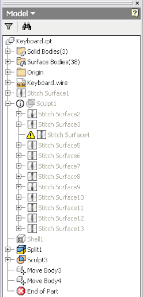
- Although not necessary, you can right-click over this node and select Delete from the pop-up context menu if you want to remove it from the Model browser. To remove the icon next to the Sculpt1 node, right-click over Sculpt1 and select Edit Feature from the pop-up context menu. When the Sculpt dialog box appears, click OK to close the dialog box and rebuild the Sculpt feature.
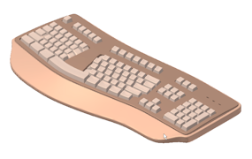
- As an optional step, move the End of Part marker above Move Body3 in the Model browser to view the revised keyboard in an unexploded representation.
- Do not save Keyboard.ipt.