- Double-click Tube & Pipe Runs in the Model Browser.
-
 On the ribbon, click
Tube and Pipe tab
 Run panel
 Create Pipe Run
.
 - On the Create Run dialog box, enter AirSystem2 as the Run File Name. Accept the other defaults and click OK.
The individual run AirSystem2:1 is added and activated in the browser. The Pipe Run tab displays on the ribbon.
- On the Pipe Run tab, Manage panel, select the Hydraulic Hose - Female Thread - Swivel style from the Active Style list.
-
 On the ribbon, click
Pipe Run tab
 Route panel
 New Route
.
 - On the Create New Route dialog box, accept the default route file name and location, and click OK.
A pipe route is added to the active run and activated. The Route tab displays on the ribbon.
-
 On the ribbon, click
Route tab
 Create panel
 Route
.
Route
.The start fitting specified by the hose style is attached to the cursor and ready for placement.

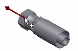
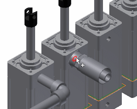
- Move the cursor on the circular edge as shown in the following image. Then click to set the start fitting.Note: The direction axis on the part must point in the direction of the route.

- The end fitting appears and is attached to the cursor. Notice that the start fitting and end fitting reference the same part in this style.
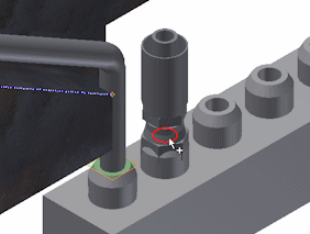
- Move the cursor to the circular opening on the valve part.
If the orientation of the fitting is not correct, right-click and select Next Connection.

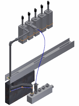
- Click to place the end fitting. The route line displays.
