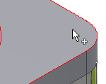
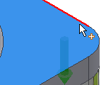
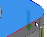
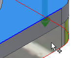
Insert bolted connections
|
|
- On the ribbon, click
Design tab
 Fasten panel
 Bolted Connection
.
 Note: To insert bolted connection using Bolted Connection Generator, your assembly must contain at least one component. (It is necessary to place the bolted connection).
- On the Design tab:
- In the Type area, select the type of bolted connection. (If your assembly contains only one component, select Through All connection type.)
- Select the type of placement from the Placement pull-down menu. Set Linear to specify placement by selecting two linear edges. Set Concentric to specify placement by selecting the circular edge. Set On point to specify placement by selecting a point. Set By hole to specify placement by selecting a hole.
- Specify position of the bolted connection. According to your placement selection, you are prompted to specify start plane, edges or point or hole, and termination plane. Displayed options depend on your selected placement type.
Note: If you do not specify the bolted connection placement you are not able to select fasteners to the bolted connection. Bolted Connection Generator filters the fasteners selection based on placement specifications made on the left side of the Desig tab. When the placement specifications are not done, selection of fasteners on the right side of the Design tab is not enabled.
If you insert a bolted connection to an assembly that contains two or more components and select Blind Connection type, in the Placement area you are prompted to select Blind Start plane (not termination plane) to specify where the blind hole starts
- In the Thread area, specify the thread type from the Thread pull-down menu, and then select the Diameter dimension.
- Begin populating the bolted connection. Follow the instructions on the right side of the Design tab. Click "Click to add a fastener" to connect to the Content Center where you select the component.
Then, generator automatically offers you the next logical type of fastener for your bolted connection. For example, you are offered to add a washer after you selected a bolt. In the dialog box with displayed available components you can however change the category, and select a nut, for example. Also, you can filter displayed components by selecting a standard.
Note: You must connect to the Content Center server and Content Center must be configured on your computers to insert components using Bolted Connection Generator.
- Continue populating the connection by selecting appropriate content.
|
|
|
- (Optional) Click More in the right lower corner of the Design tab to open the More Options area, where you can save your bolted connection to the templates library. Click Add and specify the template description.
- Select OK to insert bolted connection to the assembly.
Note: If you select Apply, Bolted Connection Generator remains opened.
|
Insert bolted connections using linear placement option
Select linear type of placement to specify the bolted connection position by selecting two linear edges.
|
|
- On the ribbon, click
Design tab
 Fasten panel
 Bolted Connection
.
 Note: To insert bolted connection using Bolted Connection Generator, your assembly must contain at least one component. (It is necessary for bolted connection placement).
- In the Type area of the Design tab, select the type of hole.
|
|
|
- Select Linear from the drop-down list in the Placement area of the Design tab.
- In the graphics window:
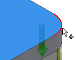
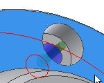
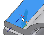
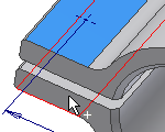
- Select the start plane. After the selection, other buttons for placement are enabled (Linear edge 1, Linear edge 2, Termination).
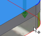
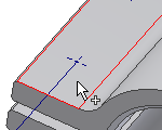
- Select first linear edge.
- Select second linear edge.
- Select the termination plane.
|
|
|
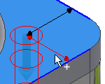
- In the graphics window, click the 3D grip to edit the distance of hole center from selected linear edges. Click the button to confirm the distance.
- In the Thread area, select the type and diameter of thread.
- Click the “Click to add a fastener” text in the right area of the Design tab and populate the bolted connection.
|
|
|
- (Optional) Click More in the right lower corner of the Design tab to open the More Options area, where you can save your bolted connection to the templates library. Click Add and specify the template description.
- Select OK to insert bolted connection to the assembly.
Note: If you select Apply, Bolted Connection Generator remains opened.
|
Insert bolted connections using concentric placement option
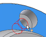
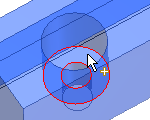
Select the concentric type of placement to specify bolted connection placement by selecting the circular edge or edges. Hole for bolted connection placement is inserted into the center of circle defined by circular edge.
|
|
- On the ribbon, click
Design tab
 Fasten panel
 Bolted Connection
.
 Note: To insert bolted connection using Bolted Connection Generator, your assembly must contain at least one component. (It is necessary for bolted connection placement).
- In the Type area of the Design tab, select the type of hole.
|
|
|
- Select Concentric from the drop-down list in the Placement area of the Design tab.
- In the graphics window:
- Select the start plane. After the selection other options for placement are enabled (Circular reference, Termination).
- Select circular edge.
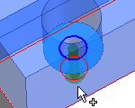
- Select the termination plane.
- In the Thread area, select the type and diameter of thread.
- Click the “Click to add a fastener” text in the right area of the Design tab and populate the bolted connection..
|
|
|
- (Optional) Click More in the right lower corner of the Design tab to open the More Options area, where you can save your bolted connection to the templates library. Click Add and specify the template description.
- Select OK to insert bolted connection to the assembly.
Note: If you select Apply, Bolted Connection Generator remains opened.
|
Insert bolted connections into patterned holes
When you create patterned holes using the Autodesk Inventor Hole command as multicenter point holes, you can insert bolted connection into such patterned holes using Bolted Connection Generator. The generator recognizes that your design contains the pattern and enables an option to insert bolted connection into patterned holes.
|
|
- Place hole feature in a part environment.
- Create the hole pattern in a part environment (not in an assembly).
- Return to the assembly from editing the part.
- Open the Bolted Connection Generator.
- In the Type area of the Design tab, select the type of hole.
|
|
|
- Select By hole from the drop-down list in the Placement area of the Design tab.
- In the graphics window:
- Select the start plane.
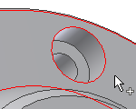
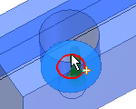
- Select the Existing hole. When your design contains a patterned hole, the Follow Pattern box is enabled.
- Select the termination plane.
- In the Placement area of the Design Tab, check Follow Pattern box. A bolted connection is inserted in every patterned hole.
- In the Thread area, select the type and diameter of thread.
- Click the “Click to add a fastener” text in the right area of the Design tab and populate the bolted connection.
- Click OK.
When you insert bolted connection into pattern, you delete all bolted connections inserted into such pattern.
|
Insert bolted connections to sketched points
If your assembly contains point created in sketch environment you can insert bolted connection to such points.
Note: You cannot insert bolted connection into sketch points created in an assembly environment.
|
|
- Create points in sketch environment.
- Return to the assembly from editing the part.
- Open the Bolted Connection Generator.
- In the Type area of the Design tab, select the type of hole.
|
|
|
- Select On point from the drop-down list in the Placement area of the Design tab.
- In the graphics window:
- Select the start plane.
- Select the point. When your design contains a sketched point, the Follow Pattern box is enabled. By default, bolted connections are inserted into every sketched point. To add or remove points, hold the Ctrl key + select the point.
- Select the termination plane.
- In the Thread area, select the type and diameter of thread.
- Click the “Click to add a fastener” text in the right area of the Design tab and populate the bolted connection.
- Click OK.
During edit, you can also add or remove bolted connections from patterned points. In the assembly, right-click and select Edit Using Design Accelerator. On the Design tab, click Points. In the graphics window, click the point from which to remove the bolted connection. Hold the Ctrl key to remove more bolted connections from point at the same time
Bolted connections inserted using Bolted Connection generators are mated to selected points. When, within the sketch environment, you move the points, all inserted bolted connections are moved also.
|
Insert bolted connection onto extruded or revolved cuts
It is also possible to insert bolted connection into holes created using Extrude and Revolve commands in part environment.
|
|
- Create holes using Revolve or Extrude commands in part environment.
- Return to the assembly from editing the part.
- Open the Bolted Connection Generator.
- In the Type area of the Design tab, select the type of hole.
|
|
|
- Select Concentric from the drop-down list in the Placement area of the Design tab.
- In the graphics window:
- Select the start plane.
- Select the circular edge. When your design contains a patterned hole, the Follow Pattern box is enabled. By default, bolted connections are inserted into every patterned hole.
- Select the termination plane.
- In the Thread area, select the type and diameter of thread.
- Click the “Click to add a fastener” text in the right area of the Design tab and populate the bolted connection.
- Click OK.
|
How to populate bolted connections
Selection of fasteners to the bolted connection is done on the right side of the Design tab. When you open Bolted Connection generator and select the bolted connection placement, the right side area is prepared for fasteners selection. Based on your placement, bolted connection filters the Content Center and enables you to insert fasteners.
To start populating bolted connection, click “Click to add a fastener” text in the gray field on the right side in the Design tab. When you click the text, you are connected to Content Center. Available fasteners are displayed. You can specify the Standard and Category of a fastener to narrow the selection.
Bolted connection offers you to select fasteners in logical order - bolts first, then washers and nuts. To change the fastener, select other offered category. For example, you want to insert two washers so select washer in the Category menu when nuts are displayed.
“No more fasteners” text means that it is not logical to insert another fastener to the position.
To change the fasteners in the designed bolted connection, select the fastener and click  .
.
Click  to open the Table dialog box. Table dialog box offers a selection of other fasteners for selected category, if possible. You can select part with other material, for example.
Note: Table dialog box is not available for holes.
Tip: Select bolt, hold the Alt key while opening the dialog box and
Modify length/hole dialog box dialog box opens. Change the bolt length there. This options as available for bolts only.
Use sheet metal fasteners in bolted connections
Using bolted connection generator, you can insert sheet metal nuts only.
Specify placement of bolted connection using steps previously and begin populating bolted connection. Select a bolt.
To select a sheet metal nut, click Click to add a fastener text. In the dialog box, have All options selected in the Standard drop-down menu ,and Sheet Metal Nuts in the Category drop-down menu. Click to select a sheet metal nut. A nut is inserted into the Design tab of the Bolted Connection Generator.
Finish populating bolted connection and click OK.
To change the sheet metal nut in the designed bolted connection, select the nut and click  .
.
Click  to open the Table dialog box. The Table dialog box offers a selection of other nuts, if possible. You can select part with other material, for example.
Add bolted connections to Templates Library
You can save the bolted connections to Templates Library.
To display the Templates Library, on the Design tab, click  More in the lower right corner.
In the Templates Description dialog box, set the template name, and click OK.
Additional insertion of connection components
|
|
- Open the Autodesk Inventor assembly with the already inserted Design Accelerator bolted connection.
- Select the bolted connection, right-click to display the context menu and click the Edit Using Design Accelerator command.
- In the right side of the Design tab, add or delete components.
- Click OK to insert updated bolted connection.
Note: You can add or delete any component from the bolted connection. When you delete a bolt, all fasteners are deleted also.
|
Calculate bolted connection
|
|
- On the ribbon, click
Design tab
 Fasten panel
 Bolted Connection
.
- In the Design tab, design your bolted connection (follow the instructions described in the first procedure previously).
- Switch to the Calculation tab.
- Use the drop-down list to select the type of strength calculation.
- Enter the calculation values. You can change the values and units directly in the edit fields.
|
|
|
- To perform fatigue calculation, click the Fatigue Calculation tab.
Note: Fatigue Calculation tab enables if you click the Enables/disables fatigue calculation command in the upper-right corner in the Calculation tab.
- Click Calculate to perform the calculation
- Calculation results are displayed in the Results area. The inputs that fail the calculation are displayed in red (their value does not correspond with other inserted values or calculation criteria). Reports of the calculation are displayed in the Summary of Messages area which is displayed after clicking the chevron in the right lower part of the Calculation tab.
- If calculation indicates design compliance, click OK.
|
 Bolted Connection Tutorial
![]() .
. ![]() to open the Table dialog box. Table dialog box offers a selection of other fasteners for selected category, if possible. You can select part with other material, for example.
to open the Table dialog box. Table dialog box offers a selection of other fasteners for selected category, if possible. You can select part with other material, for example. ![]() .
. ![]() to open the Table dialog box. The Table dialog box offers a selection of other nuts, if possible. You can select part with other material, for example.
to open the Table dialog box. The Table dialog box offers a selection of other nuts, if possible. You can select part with other material, for example. ![]() More in the lower right corner.
More in the lower right corner. 
