In this section, you define the patching and runoff surfaces for the mold assembly.
- On the ribbon, click Core/Cavity tab > Parting Design panel > Create Patching Surface
 .
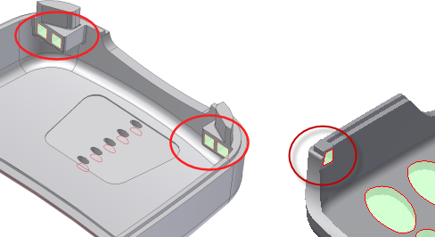
. - Click Auto Detect to start the calculation. Orient the model and then locate the circled patches, on each end of the model as shown in the following image. These patches must be created by using inserts so these patching surfaces must be deleted.

It is important to keep in mind that the Inventor Mold Design patching algorithm is a starting point for patching surfaces. Review the patching surfaces that the system detected. Add or delete patches depending on your requirements and what was automatically created for you.
- Determine the name of each patch to delete by placing your mouse pointer on each of the patches in the graphics window. Note the names that appear.
- In the Create Patching Surface dialog box, scroll through the list of patches and locate any one of the patches identified in the previous step. Select this patch and in the graphics window verify that the required patch is highlighted. Press Delete on your keyboard to remove the patch.
- Delete the other surface patches shown in the image. Ensure there are no patches on any of the four square cutouts, and that you have not deleted any of the other surface patches in the model.
- To achieve higher-quality surfaces in the final product, click All Lower
 in the Create Patching Surface dialog box to switch the patching surfaces to the lower edges of the model.
 - Click OK on the Create Patching Surface dialog box to generate the patching surfaces.
- On the ribbon, click Core/Cavity tab > Parting Design panel > Create Runoff Surface
 .
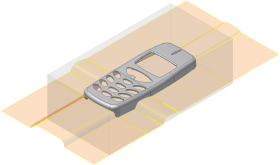
. - Click Auto Detect to start the calculation. Click OK on the Create Runoff Surface dialog box to generate the surface shown in the following image.
