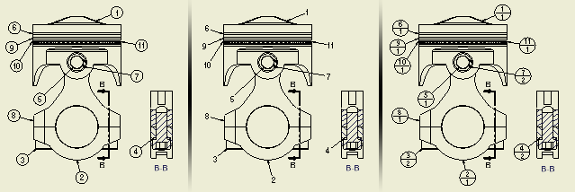
If you create a parts list before adding balloons, the balloons use properties specified by the parts list. If the view does not have an associated parts list, the BOM Properties dialog box opens so you can set the properties.
The following image shows how balloons update per changes to balloon properties.

Add balloons to individual parts
|
|
Continue placing balloons. When you finish, right-click, and then select Done to quit.
|
If a parts list is not created in the drawing or for a selection, the BOM Properties dialog appears. You can specify the BOM view during the balloon command. The balloon command continues only after properties are specified.
Use the following procedure to create balloons before a parts list:
|
|
|
Automatically add balloons to multiple parts
Use Auto Balloon to create multiple item balloons for selected components in drawing views.
|
|
Note: To add balloons for subassembly components in a view with a nested parts list, right-click the view in the browser, and then select Show Contents before clicking Balloon.
|
Attach a balloon for another part to an existing balloon
- Right-click an existing balloon, and select Attach Balloon from the menu.
- Select a part in the view to specify the balloon to attach.
- The new balloon is automatically attached to the existing balloon.
Attach balloons from list
- Right-click a balloon in the drawing and select Attach Balloon From List.
- In the Attach Balloon dialog box, click the arrow on the Filter list and select the parts to display in the list.
- In the table, select parts for which you want to create and attach a balloon.
If appropriate, right-click in the table and choose an option: Select All, Clear All, or Invert Selection (to select all unselected parts or clear the selection of all selected parts).
- When parts are selected, click OK. Balloons are attached automatically.
Create a balloon for a custom or virtual part
If you have a virtual part in the assembly, or a custom part defined in the parts list, you can create a balloon for it. The balloon can be attached either to a part in the drawing or to an existing balloon.
To place a new balloon:
|
|
Continue placing balloons, right-click, and select Done to end the operation. |
