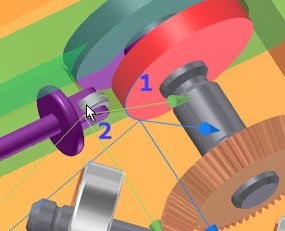
The next relationship that needs to be built is one between the cam Follower Roller and the cam component. The Follower Roller needs to contact the cam.
Retaining degrees of freedom
The Follower Roller is a symmetrical part and, by default, dynamic simulation attempts to reduce symmetrical component movement. Why? An example will help.
Consider a wheel assembly. You have a tire mounted to a rim. That assembly is attached to the vehicle with lug nuts.The function of a lug nut, for simulation purposes, isn’t to revolve around its axis; it is to constrain the assembly to the vehicle. Because the lug nut is a symmetrical component, the rotational degree of freedom (DOF) is automatically removed. This simplifies the model for simulation purposes. If you want to retain the lug nut’s rotational DOF, you can do so using the Retain DOF command. The same is true in reverse. That is, you can use Ignore DOF to restrict the degrees of freedom of a component.
To ensure that the Follower Roller contacts the cam while also keeping its degree of freedom:
- In the Mobile Groups folder, expand the Welded group. There are two components in the group.
- Right-click the Follower Roller component, and click Retain DOF.
The roller retains its motion characteristics. Now, we need to make sure the roller contacts the cam.
- Click the Insert Joint command to display the dialog box. From the list, select 2D Contact.
- Select the cam profile edge.
- Select the sketch profile displayed on the roller component. As you can see, you can use sketch geometry as part of the simulation.

- Click OK.
- Drag the Follower until it contacts the cam. It makes contact but does not penetrate the cam. The 2D contact established a mechanical relationship between the two components.
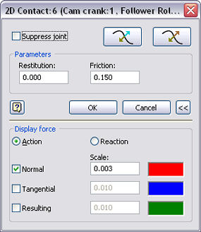
Before going any further, we will modify the properties of the 2D contact and display the force vector.
- In the browser, right-click the 2D contact joint, and click Properties.

- Set the Restitution value to 0.0, and Friction to 0.15.
- Expand
 the dialog box to access the lower section. Check the Normal box, and set the Scale to 0.003.
 - Click OK.