Now we need to build the relationship between the bevel gears.
There are two bevel gears, a larger one associated with the cam action, and a smaller one associated with the motor assembly. We will work with the smaller gear to start with.
- Expand the Mobile Groups folder and Motor node to reveal the Bevel Gear1 node.
- Right-click the Bevel Gear node and click Edit.
You are automatically placed in the Part editing environment.
- In the browser, expand the Surface Bodies(1) folder.
- Right-click the Srf1 browser node, and click Visibility.
We will use the surface to help define the bevel gear relationship.
- On the ribbon, click Return
 to go back to the simulation environment. Alternatively, right-click in the graphic area, and click Finish Edit.
 - On the ribbon, click
Dynamic Simulation tab
 Joint panel
 Insert Joint
 to display the Insert Joint dialog box.
 - In the drop-down list, select Rolling: Cone on Cone.

- The component selector
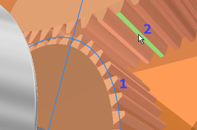
 is automatically active, allowing you to begin selection. Select the Pitch diameter circle at the base of the surface cone.
 - Click the component 2 selector
 , and select a conical face on Bevel Gear2.
 You may have to expand the Mobile Groups and Cam crank browser nodes to see the second gear.

- Click OK.
- Click and drag the motor bevel gear. The Cam crank assembly moves because of the joint you created.
- Edit the part again, and turn off Visibility of the Srf1 surface body.