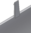
Creates a Snap fit feature using points of 2D sketches or 3D work points and direction elements.
Access
Ribbon:
3D Model tab
 Plastic Part panel
 Snap Fit
![]()
| Style specification | ||
|
|
Cantilever Snap Fit Hook style |
 |
|
|
Cantilever Snap Fit Loop style |
 |
Shape tab
Common to both styles. Specifies the placement of the Snap fit.
| Placement | ||
|
|
Solid specifies the target body of the Snap fit feature. | |
| From Sketch placement requires points on a sketch plane (Centers). | ||
 |
Flip beam or clip direction flips the direction (that initially corresponds to the sketch plane normal). | |
|
|
Centers specifies the center location. Points created using the Center Point switch are automatically selected. | |
|
|
Hook Direction provides four arrows to choose from, at 90 -degree intervals . | |
| On Point placement requires 3D work points or sketch points (Centers), and two directions. | ||
 |
Flip beam or clip direction defines the direction. | |
 |
Beam Direction flips the direction opposite to the vector defined by the Direction selection. | |
|
|
Hook/Catch direction selector specifies the direction of the hook/catch when On Point is specified. | |
|
|
|
Hook direction provides four arrows to choose from, at 90 -degree intervals . |
The Extend check box specifies whether to extend or stop the beam:
 |
|
 |
|
Beam tab (Cantilever Snap Hook style)
Specifies the beam parameters of the Snap fit feature.
 |
Beam thickness at the wall |
 |
Beam length |
 |
Beam thickness at the hook |
 |
Beam width at the wall |
 |
Beam width at the hook |
Hook tab (Cantilever Snap Hook style)
 |
Hook tip length |
 |
Hook undercut depth |
 |
Hook length |
 |
Hook retention face angle |
|
|
Hook insertion face angle |
Clip tab (Cantilever Snap Loop style)
 |
Clip length |
 |
Clip width |
|
|
Beam thickness at the wall |
|
|
Beam thickness at top |
Catch tab (Cantilever Snap Loop style)
 |
Catch width at the sides and top |
 |
Catch opening length |