 |
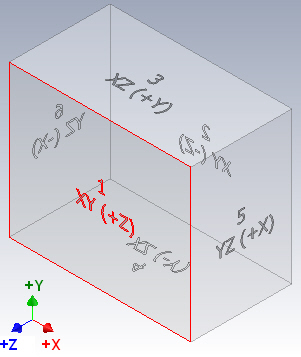
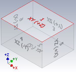
Default isometric view in English template. (See Default isometric view in Metric template.) The view orientation (Front, Top, Left, Right, and so on) being used in IDW, Autodesk Inventor View, and 3D DWF are defined by the following mapping. The mapping is fixed and cannot be changed. The table refers to the parts origin plane when placing a drawing view. |
|
|
Origin folder in IPT and IAM |
View orientation in IDW, 3D DWF, and Autodesk Inventor View |
|
|
XY (+Z) |
1 = Front |
|
|
XY (-Z) |
2 = Back |
|
|
XZ (+Y) |
3 = Top |
|
|
XZ (-Y) |
4 = Bottom |
|
|
YZ (+X) |
5 = Right |
|
|
YZ (-X) |
6 = Left |
|
|
For example, XY (+Z) means that you look at the XY Plane from +Z. Note: Redefining the isometric view in an .ipt or .iam file does not affect the mapping previously described.
|
||
Default isometric view in Metric template
 |
To redefine an isometric view
|
