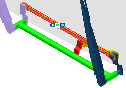
- On the toolbar located at the top of the Output Grapher, select the Export to FEA command.

You are prompted to select a part to analyze.
- Select the Crank Sway part. You can orbit the assembly or use Select Other to access the part.
 Note: You can select more than one part to export. You cannot select parts within a subassembly unless the subassembly is set to Flexible.
 - In the Export to FEA dialog box, click OK.
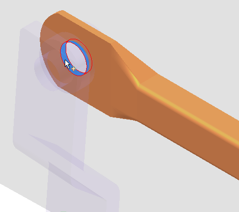
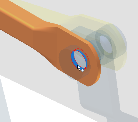
Next, you specify the load bearing faces. For this part, the holes on either end of the arm contain the load bearing faces.
- For the Point-Line joint, select the face as shown.

- In the dialog box, select the Revolution joint to complete the field.
- Select the other face as shown.
 Note: Alternatively, you could use the Automatic Face Selection option to allow the software to select the load-bearing faces automatically.
 - Click OK.
The loads are exported and ready for retrieval in Stress Analysis.
- Close the Output Grapher.