To define constraints and loads, use the commands available in the ribbon panels. Alternatively, right-click the browser node for the input type, and click the command there.
- On the ribbon, click
Stress Analysis tab
 Constraints panel
Fixed
.
Constraints panel
Fixed
.
The dialog box displays with the Face selector active.
- Choose the appropriate faces. Multiple faces can be selected. In this case, the faces represent a rigid attachment that occurs later in the manufacturing process.
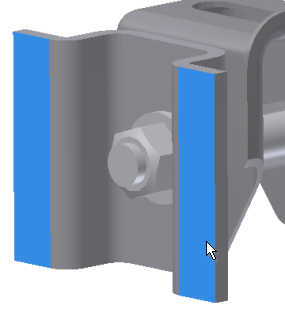
- Click OK to complete the constraint inputs.
Add the second constraint:
- Click the Fixed command.
- Select the cylindrical faces of the slot feature.
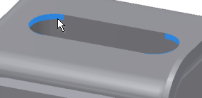
- Click OK.
Next, we add a force or load. These steps define a condition where the assembly receives a constant load in a given direction.
- Click
Stress Analysis tab
Loads panel
Force
.

The dialog box displays.
- Choose the flat face at the bolt head.
- Click the
 More command to expand the dialog box, and check Use Vector Components.
 - For the Fz component, enter 225. It defines the force magnitude and direction.
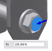
- Click OK.
We now have defined materials, structural load, and constraints. In the browser, expand the Constraints and Loads nodes for viewing. Click a node to highlight the selection or location in the graphics window; and double-click to edit the definition.