You define contacts manually by selecting pairs of faces; these contacts are useful for cases in which the initial default contact tolerance is too small. Before manually adding contacts, use Automatic Contacts to detect the in-tolerance contact conditions.
- In the Contacts panel, click Automatic
 . Contact conditions are automatically defined using the Contact defaults from the Stress Analysis Settings.
As you manually add contacts, you choose from various contact types such as Separation, Sliding / No Separation, and so on.
We will now define manual contacts and set them to the Separation type. Additionally, we will modify two automatically created contacts to be the Separation type.
- Click the Manual
 command.
 - Set the Contact Type to Separation.
- Select the faces for the new contacts as follows
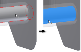
- In the graphics region, click the Bolt cylindrical face as selection 1.
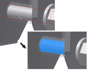
- Move the cursor over the area where the Bolt component passes through the Bracket. When the cylindrical face on the Bracket highlights, click to select it.
- Click Apply.
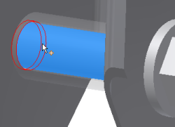
- Reorient the model to do the same for the similar area near the Bolt head.
- Click the cylindrical face of the Bolt component.
- Move the cursor over the area where the Bolt component passes through the Bracket. When the cylindrical face on the Bracket highlights, click to select it.
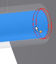
- Click OK.
-
Now, we modify two automatic contacts to change them to the Separation contact type.
- In the browser, expand the Contacts and then the Bonded folders.
- Select contact Bonded:1, then hold down the Ctrl key and select contact Bonded:2.
- Over one of the selected contacts, right-click and select Edit Contact.
- Select Separation from the Contact Type drop-down list. It assigns the selected contact condition.
- Click OK.
With the contact conditions defined, we can move to specifying the mesh settings.