We now add a unique feature to the back cylinder cap. Use the Mirror command to create an identical feature on the opposite side of the part.
Creating a feature and then mirroring it allows symmetrical features to be controlled by the original feature. When you edit the first instance, the mirrored feature automatically updates.
-
 Start the Hole command.
 - In the Hole dialog box, set the Placement to Concentric and the hole type to Counterbore.
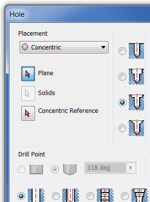
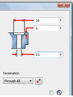
- Set the counterbore diameter to 26 mm.
- Set the counterbore depth to 6 mm.
- Set the drill diameter to 10 mm.
- Set the Termination to Through All.
- Click the Plane selection arrow in the dialog box, and then select the front plane of the revolved shape. The hole is previewed and the select arrow is moved to Concentric Reference.
- On the model in the graphics window, choose the edge of the revolved shape to define the concentric edge.
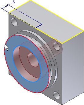
- Choose OK to create the hole.
-
 Start the Hole command. Set the Placement to From Sketch, and select the end of the 6-mm line to locate the hole.
 - In the Hole dialog box.
- Set Hole Type to Drilled.
- Set Termination to To.
- Set Hole to Tapped.
- Set Thread Type to ANSI Metric M Profile.
- Set Size to 5.
- Set Designation to M5 x 0.8.
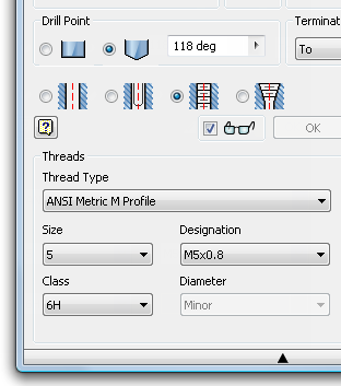
- Select the interior of the counterbored hole on the model to define the To termination, and then click OK to create the hole.
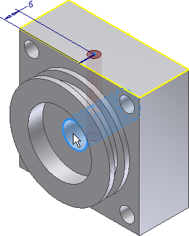
- Start a sketch on the side of the cylinder block shown in the following image.
-
 Place a Point, Center Point near the middle of the face, and constrain it to be horizontal and vertical to the outside edges.
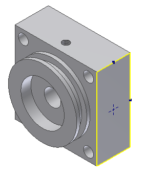
- Finish the sketch.
-
 Start the Hole command. Set the Placement type to From Sketch.
 If there are no other sketches in the model, Autodesk Inventor selects the point. If there are other sketches present, pick the point.
- Set the hole type to Drilled, the hole diameter to 10 mm, and the hole depth to 10 mm.
- Click OK to create the hole.
-
 On the ribbon, click
3D Model tab
 Pattern panel
 Mirror
.
 - The feature selection arrow is active. Select the inside of the hole you just created to add it to the mirror.
- Change the selection type to Mirror Plane. You can do it in the dialog box, or you can right-click and choose Continue from the pop-up context menu.
- In the Model browser, under the Origin folder, pick YZ plane to define the mirror plane.
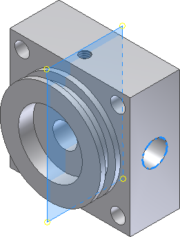
- Click OK to mirror the feature.
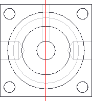
- Save and close the file.