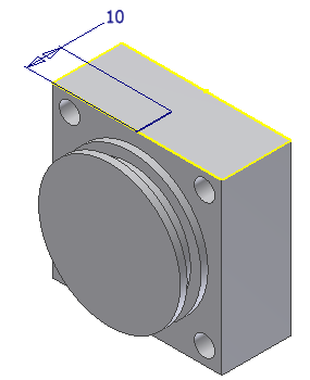
In the next series of steps, we edit the sketch to move the tapped hole location to demonstrate a feature edit and to show the associativity between features.
In this scenario, a change order was submitted stating that the tapped hole on the front cylinder cap must be located in the middle of the part. To begin:
- Locate the tapped hole in the Model browser. If you did not delete any holes in the first part of the exercise, it should be named Hole2 in the browser.
- Click + next to the hole feature to expose the sketch beneath the feature. Right-click the sketch, and choose Edit Sketch from the context menu.Tip: You can also choose Edit Sketch with a right-click on the feature without exposing the sketch.
- Double-click the 6-mm dimension to enable the edit box. Change the 6-mm dimension to 10 mm.
Notice that when you edit a sketch, the part history is “rolled back” to the feature state that existed at the time the sketch was created.

- Exit the sketch. The tapped hole, the work plane, work axis, and 4-mm hole are updated.
- Save the file and close it.
- Open the file End Cap Back.