In this topic, you examine the files that are created for the mold base runner system, and some other mold assembly component commands.
To create the runner system in a mold assembly, define the gate location, runner sketch, runner, gate, and cold well. With the initial definition of the gate location, an _RG (Runner) file is created in the Cover Mold folder. Review the CoverMold_RG.ipt file in the Model browser. The _RG file is an adaptive file, as indicated by the adaptive symbol at the beginning of the file name ![]() . As each item that makes up the runner system is created, the _RG file updates all the information.
. As each item that makes up the runner system is created, the _RG file updates all the information.
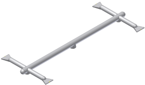
- Right-click CoverMold_RG.ipt and select Open. The runner appears as shown in the following image.

- Click Close
 to close this model.
 - Review the Mold Design browser. The Runner, Gate, and Cold Well nodes were added to the model when these commands were executed on the mold assembly.
When you add Ejecting Components, Sliders, Sprue Bushings, Locating Rings, and Lifters, folders are also created for all their generated components. For example, the following folders were created in this assembly:
- Ejectors
- Lifters
- Locating Ring
- Sliders
- Sprue Bushing
The files in each folder are generated from the mold libraries. For any command that can generate multiple components, multiple groups are created in its folder. For example, a Group N.0 folder is generated for each ejector pin grouping that is added to the assembly. There is only one grouping of ejector pins in the CoverMold.iam mold assembly so the folders appear as follows:

- Ejectors (1)
- Type (2)
- Group (3)
- In Windows Explorer, navigate to the Cover Mold Ejectors folder to review the files and discover the naming conventions for files generated from the libraries. Also expand and review the following folders:
- Lifters
- Locating Ring
- Sliders
- Sprue Bushing
- Review the Model browser display and notice the following near the bottom of the browser:
- The _AG 156-7-0 file was created when the sprue bushing was inserted.
- The _DHR 21 100-12 file was created when the locator ring was inserted.
- Expand the _LY and one of the _PZ assemblies. The six Group 1 _Ejector Pin# models are located here because they were used to eject the plastic part.
- Review the Mold Design browser display and notice the nodes in the browser. The order in which the following nodes are listed indicates the order in which they were added to the mold assembly: Ejecting Components, Slider Assemblies, Sprue Bushing, Locating Ring, Lifter Assemblies.