In this topic, you examine all the files that are created in the mold assembly to generate the core and cavity. You also examine the files created by the addition of the mold base.
- Review the Mold Design and Model browser displays. With the addition of the workpiece, a _WP file is generated when the assembly is saved. This _WP part file contains a single extrude feature that creates the workpiece geometry. In the cover node in the Mold Design browser, a Workpiece node indicates that the workpiece was added. In the Model browser, the workpiece file is located in the Part Zone (_PZ) assembly.
- When creating the parting surface, you first create a patch surface and then you create the runoff surfaces. Although no new files are created during this step, the _MP file is modified. The only change to the Mold Design browser display is that Patching Surfaces and Runoff Surfaces nodes are now listed in cover.
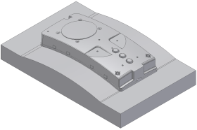
- With the creation of the core and cavity, a Core file (_CR) and a Cavity file (_CV) are generated, and a Core Cavity node is added to the cover node in the Mold Design browser. These files are located in the Part Zone (_PZ) assembly.
- In the Model browser, expand the _LY and _PZ assemblies, right-click the CoverMold_cover_CR file, and click Open.

CoverMold_cover_CR
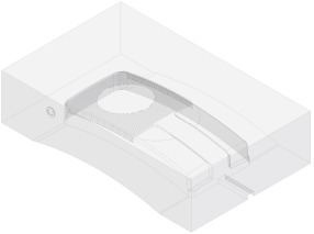
- To return to the mold assembly, click the CoverMold.iam tab at the bottom of the working window. Right-click the CoverMold_cover_CV file and click Open. Review the geometry in both these parts. The geometry of these files was based on the moldable part.

CoverMold_cover_CV
- Click Close
 in the top right-hand corner of the working window to close the two part models. The mold assembly should now be the active model. The geometry in these models can be modified directly within their individual part files. However, if changes are required to the geometry of the core/cavity that was generated by the moldable part, return to the _MP file for editing.
 - The CoverMold_cover_IN1 part file that is listed in the Cover Mold directory is an Insert. It was created when the Insert was added to the moldable part. The _IN1 file is located in the _PZ assembly. Switch to the Mold Design browser display. The Insert is included at the bottom of this list in the cover node because it was applied to the moldable part.
The addition of a mold base to the mold assembly creates a substantial number of files. To manage these files, a single _MB assembly file is added to the mold assembly, and all its files are stored in their own assembly directory. This directory is created in the assigned mold Project file location and is named MB. A subfolder in this directory indicates the Vendor of the mold base that was selected, and all the files are generated from the mold library for this vendor. A Mold Base node is added to the Mold Design browser display.