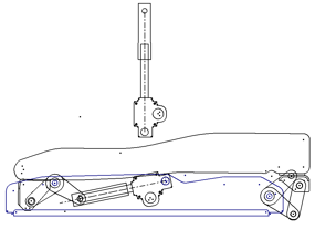
After you open the part file, note the presence of one sketch, Sketch1, in the model browser. Expand Sketch1 to view the sketch block instances. Pause the cursor over the different sketch block instances to view the associated geometry. You must add a flexible instance of the Screw Rod Assy_Front block to complete the layout.
- In the browser, double-click Sketch1 to open it for edit.
- Expand Sketch1.
- Expand the Blocks folder near the top of the browser. This folder contains all sketch block definitions.
- Drag the Screw Rod Assy_Front block from the Blocks folder into the graphics window. It adds an instance of the block to your layout.

- Right-click the Screw Rod Assy_Front:1 instance, and select Flexible. It exposes the sketch block degrees of freedom such that kinematics can be demonstrated. Screw Rod Assy_Rear:1 is already set to Flexible.
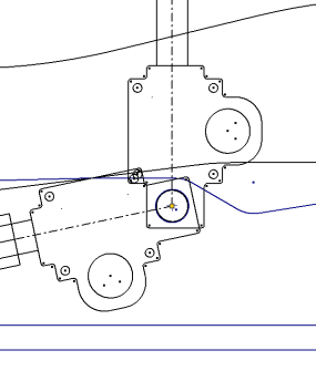
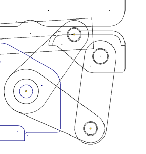
- Place coincident constraints, in the order shown, to position Screw Rod Assy_Front:1 in your layout.


- Right-click in the graphics window, and select Done to exit the Coincident Constraint command.
- Right-click in the graphics window, and select Show All Constraints to view the constraints between sketch block instances.
- Right-click, and select Hide All Constraints.
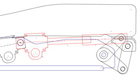
The sketch block instances are constrained in the layout. Select and drag different geometry. Note how the layout moves and demonstrates assembly kinematics. Use the Undo command to return the layout to the default position.
- Exit the sketch and save your file.