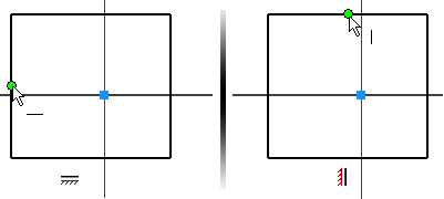
In this section, we apply horizontal and vertical constraints to constrain the shape to the X,Y, Z coordinates 0, 0, 0. We then add dimensions, create named parameters and use equations.
Constraining the rectangle centered about 0, 0, 0 makes it easy to constrain (locate) the part within an assembly. Because the Origin Work Planes pass through the middle of the part it is easy to use these planes to align the components in an assembly. Constraining a sketch to the origin also makes the sketch behavior predictable when you add driving dimensions. It also applies two constraints to the sketch by defining the Cartesian XY location.
Adding relationships between dimensions reduces the amount of edits, especially in complex parts. You can also add mathematical formulas to dimensions. A link is provided in the exercise to the operators that can be used in equations.
-
 Click the Autodesk Inventor icon to start a new part. Select New to open the Create New File dialog box.
 - Click the metric folder to start a new metric part. Under the Part category, double-click Standard (mm).ipt
 .
. If your sketch settings match the recommendations listed previously, you see an X axis, a Y axis, and a point at 0,0,0.
- Click 3D Model tab
 Sketch panel
 Create 2D Sketch.
 - Expand the Origin folder and then select the XY Plane.
If your sketch settings match the recommendations listed previously, you see an X axis, a Y axis, and a point at 0,0,0.
-
 Click
Sketch tab
 Draw panel
 Rectangle
. Select Rectangle Two Point from the drop-down menu, or select Two Point Rectangle from the marking menu. Sketch a rectangle approximately centered about 0,0.
-
 Apply a Horizontal constraint between the origin and the midpoint of a vertical line. Hover your cursor near the midpoint of the vertical line to display and select the midpoint.
 -
 Apply a Vertical constraint between the origin and the midpoint of a horizontal line. Hover your cursor near the midpoint of the horizontal line to display and select the midpoint.
 If the logic of these picks seems confusing, imagine the axis between the two points you are picking.

-
 On the ribbon, click
Sketch tab
 Constrain panel
 Dimension
, or select General Dimension from the marking menu.
 - Place a horizontal dimension.
- In the Edit Dimension dialog box, enter the equation Width=49mm to define a new variable named Width with an initial value of 49 mm.
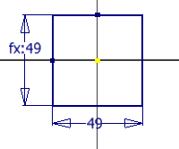
- Place a vertical dimension. Highlight the value in the Edit Dimension dialog box. Instead of entering a number, pick the horizontal dimension value. The variable name of the first dimension (Width) appears in the dialog box. Click the check mark to link the current dimension to the first dimension.
The vertical dimension displays as fx:49. The display means that a formula is in effect for the vertical dimension and the current value is 49.
- Right-click and select Done [ESC] from the marking menu to exit the Dimension command.
You have created another equation!

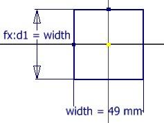
- To see the entire equation, right click in a blank area of the graphics window. Choose Dimension Display from the overflow menu, and then choose Expression. Notice the variable names and formulas appear. Each dimension is assigned a variable based on the order of creation. d0 is the first value assigned because 0 is the first integer. In this example, d0 was renamed Width and is a “driving” dimension. The second dimension retains the original variable name d1 and is “driven” by the dimension named Width. Note: The order of creation has no impact on which dimension can be the controlling dimension.
 Note: The marking menu appears near the area of the screen on which you right-click. Use this technique to control where a marking menu appears.