In this section, you create heels as features on the inserts. Heels are created on the inserts to help lock an insert into the core or cavity.
- With the template method, the heel profile is based on the following predefined types: rectangular, square, circle, key 1-flat, key 2-flats, slot, or rounded rectangle.
- With the thicken method, the heel is defined by selecting a planar face on the insert as the start plane on which to extrude the heel. An offset value for the profile of the heel is then defined.
- On the ribbon, click Core/Cavity tab > Insert panel > Create Heel
 .
. - Select Template from the Profile type menu. Select Rectangle from the Profile shape menu.
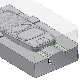
- Orient the model as shown in the following image, and select the first insert highlighted by the arrow as shown in the following image.

- Leave the Placement type as Linear. With a linear placement, you are required to select a plane and two linear references. The plane defines the surface on the selected insert in which the rectangular profile will be created. The references are edges on the selected insert that are used to locate the profile. To locate the profile correctly, Reference 1 and Reference 2 should be perpendicular to each other.
- The Face
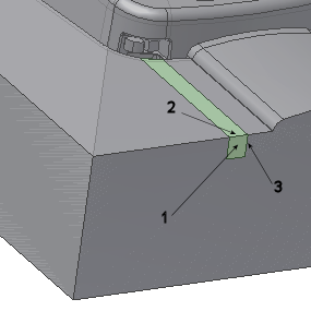
 selection tool should be active . Select the surface of the insert labeled 1 in the following image.
 - As Reference 1, select the edge of the insert labeled 2 in the following image.
- As Reference 2, select the edge of the insert labeled 3 in the following image.

- Modify the following dimensions:
- Overall width of heel = 8 mm
- Overall height of heel = 6 mm
- Distance from Reference 1 to the center = 3 mm
- Distance from Reference 2 to the center = 2 mm
- On the Create Heel dialog box, enter a Distance of 15 mm.
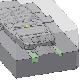
- Click Apply on the Create Heel dialog box to generate the heel. The model appears as shown in the following image.

- Create a second heel on the other insert using the profile type and shape that was used to create the first heel. Use the references shown in the following image to select the surface and edges:
- Select the surface labeled 1 as the Face.
- Select the edge labeled 2 as Reference 1.
- Select the edge labeled 3 as Reference 2.

- Modify the following dimensions:
- Overall width of heel = 8 mm
- Overall height of heel = 6 mm
- Distance from Reference 1 to the center = 3 mm
- Distance from Reference 2 to the center = 2 mm
- On the Create Heel dialog box, enter a distance of 15 mm.
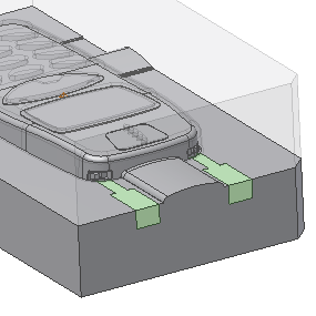
- Click OK on the Create Heel dialog box to generate the heel. The model appears as shown in the following image.

- On the Quick Access toolbar, click Save to save the assembly.