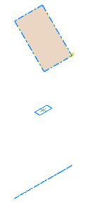
Now that the skeleton assembly has been successfully tested, you continue building the assembly. Next, create a frame part by deriving geometry from the Skeleton-frame part.
- Open Frame.iam.
- Turn off the visibility of Skeleton-frame. It prevents you from accidentally selecting the surfaces in this file in later steps.
- Click Create to create a component within the assembly.
- Enter Frame1 in the New Component Name field.
- Click
 and select Standard (mm).ipt from the Metric tab.
 - Verify that the New File Location is set to the \Tutorial Files\iCopy directory.
- Verify that Constrain sketch plane to selected face or plane is not selected.
- Click OK.
- In the Model browser, expand the Origin folder under Frame.iam and select the XY Plane.
- Exit the sketch and delete Sketch1. It is not needed for this component.
- Click the
Manage tab
 Insert panel
 Derive
command.
 - In the Open dialog box, select Skeleton-frame.ipt and click Open.
- Expand the Surface Bodies node. Set Srf1 and Srf6 to
 and all other surfaces to
  .
. - Expand the Sketches node. Set Sketch2 to
 and all other sketches to
  .
. - Expand the Work Geometry node. Set Work Plane5 to
 and all other work planes to
  .
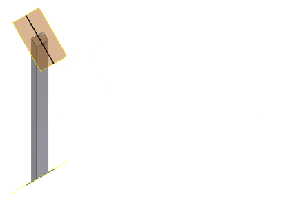
. - In the Derive dialog box, click OK. The surfaces and sketch from Skeleton-frame are added to the part. Using the Derive command to add these surfaces maintains a link between the two files. The visibility of Skeleton-frame.ipt is turned off for clarity in the following image.

- Start the Extrude command.
- Sketch2 is selected automatically. It is the only closed profile in the part.
- In the Extents drop-down menu, select Between.
- Select Srf1 and Srf6 as the Between planes. The order does not matter.
- Click OK.

- Turn off the visibility of the surfaces from the derived part (Srf1 and Srf6). It prevents you from accidentally selecting them in later steps.
- Return to the main assembly (Frame.iam).